A hot rotor left standing still will bow within minutes and can rub its seals at the next start. The barring gear, its permissive and interlock logic and a few field checks are what keep the shaft straight.
Barring gear keeps a hot turbine rotor turning slowly so it cools and warms evenly. Below is how the gear is built, how the DCS logic engages it and what to check when it refuses to start.
What is steam turbine barring gear and why is it used?
Steam turbine barring gear is a motor driven gear train that turns the turbine rotor slowly, typically 2 to 10 rpm according to EPRI, whenever the machine is hot and off steam. It stops the shaft from bowing as the top and bottom cool at different rates. For example, a rotor turned at 4 rpm for 6 hours completes 1440 revolutions, and most OEMs want at least 4 hours on barring before steam is admitted.
What Is Steam Turbine Barring Gear?
A steam turbine barring gear is a small electric motor, reduction gearbox and engaging pinion that rotate the turbine shaft slowly whenever the rotor is hot and not driven by steam. It keeps the rotor straight during cool down after a trip and during warm up before a start, so the shaft does not bow and rub its seals.
- EPRI gives a typical turning speed of 2 to 10 rpm for most steam turbines.
- The control system normally engages the gear automatically when rotor speed reaches zero after a shutdown.
- Lube oil must be in service, and jacking oil where fitted, before the barring motor can start.
- Most OEMs ask for at least 4 hours on barring before steam flow is established.
For an instrument or control engineer the hardware is simple, but the steam turbine barring gear logic is not. It ties together the lube oil console, the jacking oil pumps, speed probes, limit switches and the motor starter, and a mistake in any one of them can leave a hot rotor standing still.
Why Is Barring Gear Required in a Steam Turbine?
Barring gear is required because a hot, stationary rotor cools unevenly and bends, and a bent rotor rubs, vibrates and can even lock in its casing. Turning it slowly keeps every part of the shaft passing through the same temperature zones, so it stays straight.
Control.com describes two shapes of this temporary bend. Sagging is a downward bend from gravity combined with heat, while hogging is an upward bend caused by the hotter steam that collects at the top of the casing after a trip.
In a machine where steam is superheated to 540 °C or more, the top of the rotor can stay much hotter than the bottom for hours. If the gear fails to engage, Control.com warns that operators have only a few minutes to fix it before hogging begins, and that a hogged rotor can need extensive repair.
EPRI notes that excessive temporary bowing can lock the rotor in the casing, and its turning gear guide warns: never attempt to use steam to rotate a locked rotor.
You measure the bow with an eccentricity probe, a non contact eddy current proximity sensor that looks at a smooth shaft surface and reads the slow speed runout. API 670 covers this measurement as part of the machinery protection system.
How Does a Barring Gear Work?
A barring motor drives a worm or helical gearbox, and an engaging pinion on the gearbox output is pushed into mesh with a bull gear on the rotor coupling. Once the pinion is in mesh the motor turns the whole train at a few rpm and keeps turning until the operator or the logic stops it.
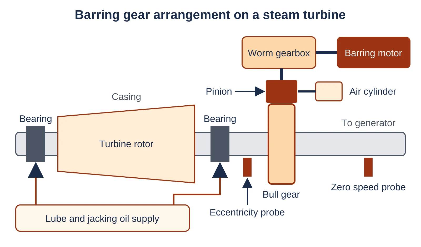
The figure shows the parts you will meet on site. A zero speed switch or speed probe watches a toothed wheel on the shaft, and the eccentricity probe sits near the bearing where the bow shows clearly.
The air cylinder that moves the pinion carries an engaged limit switch, and the barring motor sits in the MCC with its own overload and motor protection relay. Jacking oil lifts the rotor on a thin oil film so a small motor can break it away from rest.
During commissioning, stroke the engage cylinder with the motor isolated and watch the engaged limit switch on the DCS. A switch that makes before the pinion is fully in mesh will let the motor start on half a tooth.
Steam Turbine Barring Gear Logic: Permissives and Interlocks
The logic allows the pinion to engage only at zero speed with lube oil and jacking oil healthy, and allows the motor to start only after the engaged switch confirms mesh. It stops the motor on low lube oil pressure, motor overload or rotor speed rising above barring speed.
| Signal | Role in logic | Typical source | Action |
|---|---|---|---|
| Lube oil header pressure | Start permissive and trip | Pressure switch or transmitter | Block start, stop motor on low |
| Jacking oil pressure | Start permissive | Pressure switch per bearing | Block start if low |
| Rotor at zero speed | Engage permissive | Zero speed probe | Allow pinion to engage |
| Pinion engaged | Motor start permissive | Limit switch on cylinder | Start barring motor |
| Speed above barring speed | Disengage and lockout | Speed probe | Stop motor, pinion thrown out |
| Motor current high | Alarm and trip | MCC current signal | Alarm, trip on overload |
EPRI states that oil pressure sensing is part of the turning gear starting logic and that the lube oil system must be in service whenever the gear runs. Many plants wire the low lube oil pressure contact as de energize to trip so a broken wire also stops the motor.
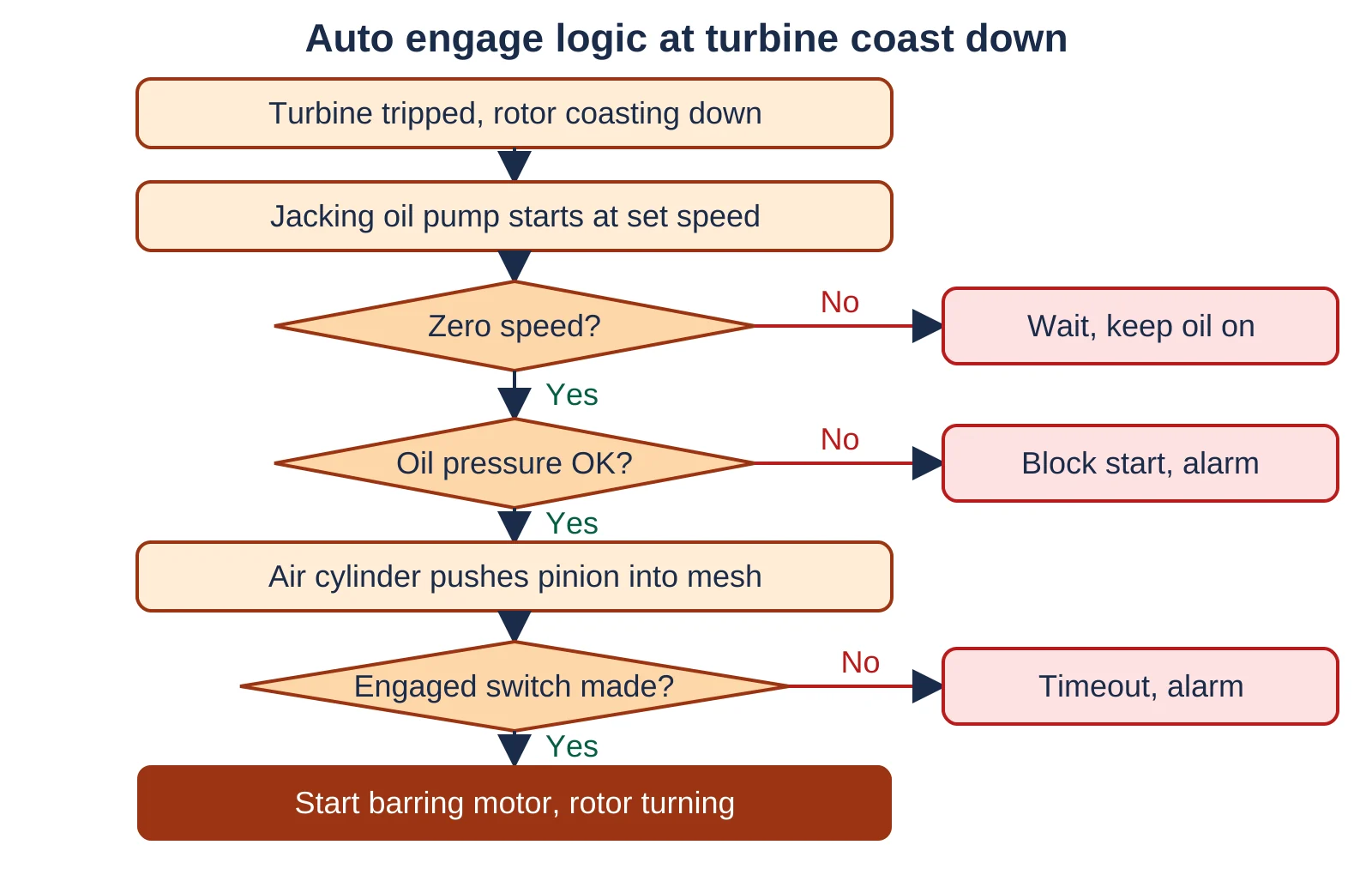
Put a watchdog on each step. A TON timer on the engage command, typically set from the OEM stroke time, raises an engage failure alarm if the limit switch does not make in time.
What Is the Speed of Turning Gear?
Most steam turbine turning gears run between 2 and 10 rpm, a range EPRI says is set by the OEM for each machine. Going below about 2 rpm can cause bearing damage, vibration and stick slip of the blades.
How Long Should a Turbine Stay on Barring?
After a shutdown the rotor stays on barring until the turbine has cooled below the OEM temperature, which can take hours to several days. Before a start, most OEMs ask for at least 4 hours on barring, and during long outages EPRI suggests about 5 hours of rotation each week.
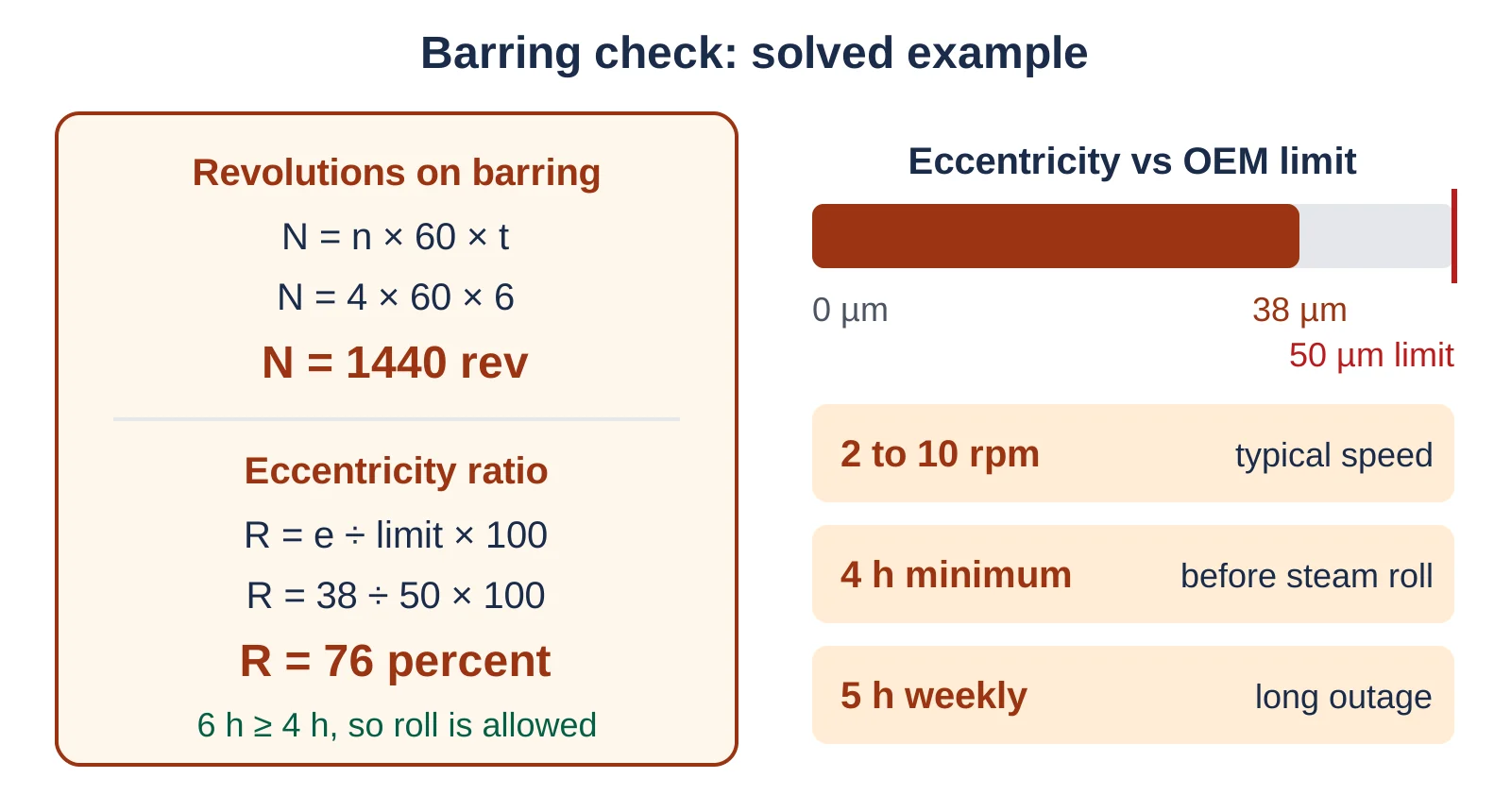
A quick check combines two numbers: how many turns the rotor has made and how close the eccentricity is to its limit. The worked example below uses a rotor at 4 rpm for 6 hours with 38 µm eccentricity against an assumed OEM limit of 50 µm.
N = 4 × 60 × 6 = 1440 rev
Eccentricity ratio: R = e ÷ limit × 100
R = 38 ÷ 50 × 100 = 76 percent
Time check: 6 h ≥ 4 h, so roll is allowed
Use the OEM limit from your turbine manual, since the 50 µm value here is only an example. If the eccentricity is still above the limit after the minimum time, keep the rotor on barring and trend the reading rather than forcing the start.
- Rotor cools and warms evenly, so it stays straight
- Eccentricity stays inside the OEM limit for the next start
- Seals and blade tips avoid rubs at run up
- Bearings see a steady oil film with jacking oil on
- Hogging begins within minutes on a hot rotor
- Rotor can lock in the casing and delay the restart
- High vibration and seal rubs at the next roll
- Extended outage for straightening or repair
EPRI notes that jacking or lift oil pumps are common on units of about 1000 MW and above, and that ALSTOM uses them on turbines above roughly 100 MW.
Barring Gear Troubleshooting
When the barring gear will not engage or start, check the permissives first, then the pinion mechanism, then the motor. The EPRI troubleshooting table follows the same order.
| Symptom | Likely cause | What to check |
|---|---|---|
| Motor will not start | Permissive missing | Starting permissive values and inputs, power to starter |
| Pinion will not engage | Speed, limit or pressure switch | Switch states on DCS, manual engage |
| Cylinder does not move | No instrument air | Air supply and solenoid valves |
| Low oil pressure trip | Lube pump not running | Pump status, sight glass flow to bearings |
| High motor current | Rubbing or bowed rotor | Eccentricity, motor windings, bearing oil |
If the motor starts but draws high current, treat it as a warning. EPRI lists excessive eccentricity and degraded motor windings among the checks, and a vibration monitoring trend from the last coast down often shows whether the rotor rubbed.
Handle any bypass of a barring permissive the way you handle a safety signal bypass, with a permit, a time limit and a log entry. Forcing the engaged switch to start the motor can strip the pinion teeth.
If the gear trips repeatedly at night, trend lube oil header pressure at one second resolution. A pressure dip at a pump changeover is a common reason the barring motor drops out.
The EPRI guide is free to download and covers turning gear design, lift oil, control logic and maintenance in depth.
The video walks through the barring gear interlocks on a real unit. You can build the same sequence in a test rack with free PLC programming software and simulated switches before you load it into the DCS.
Barring Gear vs Turning Gear: Is There a Difference?
There is no technical difference, since both terms describe the gear that slowly turns a turbine rotor. Barring gear is the common term in India and Europe, while turning gear is common in American manuals and EPRI reports.
The control side is also identical. Whatever name your P&ID uses, the same permissives, interlocks and shutdown system links apply, and the logic usually lives in the turbine control system or the BPCS rather than the SIS.
Steam Turbine Barring Gear FAQ
It turns a hot rotor slowly so it cools and warms evenly without bowing.
A bowed rotor shows high eccentricity, rubs its seals and can even lock in the casing, so barring runs after every trip until the turbine is cool and for at least 4 hours before a start.
There is no difference, since both names describe the same slow rotation gear.
Barring gear is common in India and Europe, while turning gear appears in American manuals and EPRI reports. The permissives, speed range and logic are the same whichever name the drawing uses.
The usual permissives are lube oil pressure healthy, jacking oil healthy where fitted, rotor at zero speed and pinion engaged.
The steam turbine barring gear motor trips on low lube oil pressure, overload or rotor speed rising above barring speed. Check your OEM logic diagram for the exact switch list.
Multiply barring speed by 60 and by hours to get revolutions, then divide measured eccentricity by the limit.
At 4 rpm for 6 hours the rotor makes 1440 revolutions. With 38 µm against an assumed 50 µm limit the ratio is 76 percent, so the start can go ahead.
EPRI gives a typical range of 2 to 10 rpm, set by the OEM for each machine.
Running below about 2 rpm can damage bearings and cause blade stick slip. Some hydraulic designs turn faster, and EPRI quotes one Siemens system at 20 to 150 rpm.
Most repeat trips come from a lost permissive, usually low lube oil pressure or a faulty limit switch.
Check pump changeover dips, instrument air to the engage cylinder and motor current. High current points to a rubbing or bowed rotor and needs an eccentricity check before you retry.
Related Articles
- Lube Oil Console API 614 Requirements
- Zero Speed Switch Working
- Vibration Switch for Machine Protection
- Emergency Shutdown System ESD
- First Out Alarm PLC Logic
External References
- EPRI Turning Gear Maintenance Guide, Report 1019645 (PDF)
- Control.com: Understanding Ratcheting and Turning Gears
- Wikipedia: Barring engine
What We Learn Today
- Barring gear turns a hot turbine rotor at about 2 to 10 rpm so it cools evenly and does not bow, rub its seals or lock.
- The steam turbine barring gear logic engages the pinion only at zero speed with lube and jacking oil healthy, then starts the motor after mesh.
- Most OEMs need at least 4 hours on barring before steam, and eccentricity must sit inside the OEM limit before the turbine rolls.