An iMCC puts a smart motor management relay or drive in every feeder and sends all motor data to the DCS over one network. We will go through the architecture, the data you get, the cable savings and how to fix communication loss.
An iMCC replaces hundreds of hardwired control signals with one industrial network and gives every feeder real diagnostics. We explain how it works, what it saves and how to keep it communicating.

What is an intelligent MCC and how is it different from a normal MCC?
Intelligent MCC means a normal low voltage motor control centre in which each feeder carries a smart motor management relay, VFD or soft starter connected to the DCS or PLC over Profibus, Profinet, Modbus TCP or EtherNet/IP. Instead of 7 hardwired signals per motor, one network drop carries start, stop, status, current and trip cause. For 40 motors that removes 280 IO points and 560 cores.
What Is an Intelligent MCC?
An intelligent MCC is a motor control centre whose starters, drives and meters are smart devices that measure, protect and report over an industrial network. So an intelligent MCC turns every motor feeder into a source of data on the network, for the DCS and for the maintenance team.
- Eaton calls an MCC intelligent when it is integrated with communications and smart devices.
- Typical devices are SIMOCODE pro, TeSys T, ABB UMC100.3, VFDs and soft starters.
- Common networks are Profibus DP, Profinet, Modbus TCP and EtherNet/IP.
- The power section still follows IEC 61439 2 and starters follow IEC 60947 4 1.
The power side is the same as in our guide on how a motor control center works. Busbars, withdrawable buckets, MCCB, contactor and form of separation stay unchanged, and only the control and protection layer becomes smart.
Wikipedia notes that motor control centres have been used since 1950, first by the automobile industry. The intelligent MCC is the same idea with a communication layer added decades later.
How Does an Intelligent Motor Control Center Work?
A smart relay in each feeder does protection and logic locally, while it exchanges commands and measured data with the control system over a fieldbus or Ethernet. The DCS sends a start bit, the relay closes the contactor and sends back status, current and alarms within one bus cycle.
A conventional panel needs a run relay, a separate thermal overload relay, auxiliary feedback contacts and often a 4 to 20 mA current transducer. Each signal is a pair of cores running to marshalling and then to a DCS IO card.
Because protection lives inside the relay, the motor stays protected even when the network fails. Overload, phase failure and earth fault trips work without the DCS, and the network only adds control and visibility.
Intelligent MCC Architecture and Block Diagram
The intelligent MCC architecture has three layers: the control system, a network of switches or a Profibus master, and the smart feeders with their motors. Each feeder keeps its own short circuit device and contactor, and only the control path is shared.
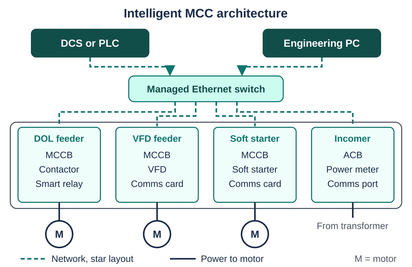
Eaton recommends home run star wiring so that a lost link drops only one feeder, and notes that managed switches can also close a ring. The same choices are covered in our article on DCS network redundancy.
Modular system in pro S and pro V versions with current, voltage and thermistor modules.
LTMR controller with 6 inputs, 3 relay outputs and CTs for 0.4 to 100 A, or 810 A with external CTs.
Universal motor controller for 0.24 to 63 A with trip classes 5, 10, 20, 30 and 40.
Drive with a network option card giving speed, current and fault codes.
Keep the emergency stop and any SIL rated trip hardwired to the contactor coil or a safety relay. Let the network only report that the trip happened.
What Data Does a Smart Motor Management Relay Give?
A smart motor management relay gives the DCS motor status, 3 phase current, thermal capacity, trip cause, warnings, run hours and starts. Devices with a voltage module also add voltage, power factor and energy.
| Data point | Source | How you use it |
|---|---|---|
| Running, tripped | Status bits | Faceplate and interlocks |
| Phase currents | Built in CTs | Dry run and choke detection |
| Thermal capacity % | Thermal model | Warn before an overload trip |
| Trip cause | Fault register | Fault finding without opening the bucket |
| Run hours, starts | Counters | Maintenance and starts per hour limit |
| kW, kWh, PF | Voltage module | Energy reports |
Schneider lists thermal overload, phase reversal, phase imbalance, ground fault, PTC thermistor and stall detection among TeSys T functions. That overlaps with the motor protection relay types used on high voltage motors.
iMCC Communication Protocols: Profibus, Profinet, Modbus TCP and EtherNet/IP
The intelligent MCC network is usually Profibus DP or Profinet in Siemens plants, EtherNet/IP in Rockwell plants and Modbus TCP in mixed vendor plants. Pick the protocol your DCS supports natively, because every gateway adds a failure point.
| Protocol | Physical layer | Watch out for |
|---|---|---|
| Profibus DP | RS 485, up to 12 Mbps | Termination, segment length |
| Profinet | Ethernet, 100 Mbps | Device names, switch settings |
| EtherNet/IP | Ethernet, 100 Mbps | EDS files, multicast load |
| Modbus TCP | Ethernet, 100 Mbps | Manual register map |
| Modbus RTU | RS 485 serial | Slow polling with many slaves |
The Siemens Smart MCC communications manual states that Profibus DP runs at up to 12 Mbps with 100 m per segment at that speed. It lists SIMOCODE pro V cyclic data of 10 input bytes and 4 output bytes in one telegram type, so even 40 motors need only a few hundred bytes per cycle.
Smart MCC vs Conventional MCC
A smart MCC differs from a conventional MCC only in the control layer, where relays, auxiliary contacts and transducers become one networked device per feeder. The power circuit and short circuit rating stay the same.
| Feature | Conventional MCC | Intelligent MCC |
|---|---|---|
| Control signals | 5 to 10 wired pairs per motor | One network drop per feeder |
| Overload | Bimetal relay | Thermal model with warnings |
| Diagnostics | Tripped lamp | Trip cause, current, counters |
| DCS IO | DI, DO, AI cards | One comms module |
| Settings | Dial in bucket | Remote, password controlled |
| Cost | Lower device cost | Lower cabling cost |
- Far fewer control cables, glands and terminals
- Trip cause visible on the DCS
- Thermal warning before a trip
- Run hours support predictive maintenance
- Less work near live parts
- Higher cost per feeder
- Needs network and cybersecurity skills
- One bad switch can blank many motors
- Firmware and device files must be managed
How Many Hardwired IO Points Does an iMCC Save?
An intelligent MCC saves N × (DI + DO + AI) hardwired IO points, where N is the number of motors. Multiply the points by 2 for control cable cores, since each signal uses one pair.
Points = N × (DI + DO + AI)
= 40 × (4 + 2 + 1) = 280 points
Cores = 2 × 280 = 560 cores
DI cards = 160 ÷ 16 = 10
DO cards = 80 ÷ 16 = 5
AI cards = 40 ÷ 8 = 5
Total = 20 IO cards
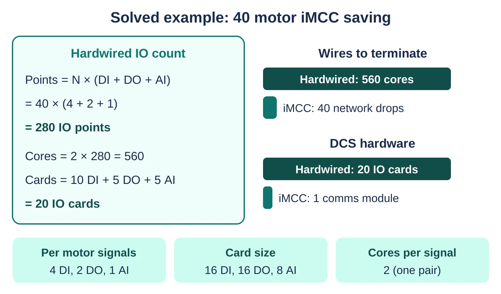
Here the 4 inputs are running, tripped, remote and available, the 2 outputs are start and stop, and the analog input is current. Check the DCS IO allocation sheet of a similar project before you fix your numbers.
The calculator assumes 16 channel digital and 8 channel analog cards without spares. To check network load, use our network bandwidth calculator with the cyclic bytes from the device manual.
A Control Engineering case study describes a retrofit with five new control panels supporting 434 motor starters. It states that intelligent motor management reduced discrete PLC IO, field wiring and installation work.
Intelligent MCC Selection and Commissioning Checklist
Select an intelligent MCC by matching the device and protocol to your DCS, then commission it in order: addressing, parameters, network test, loop check and live run. Skipping the network test before running motors causes most delays.
- Device files match the firmware version
- Emergency stop tested without the network
- FLC and trip class match each nameplate
- Parameter backups stored
- Unused switch ports disabled
Take FLC from the nameplate as explained in our note on motor full load current. The site sequence mirrors our DCS commissioning steps article.
Troubleshooting Communication Loss in an Intelligent MCC
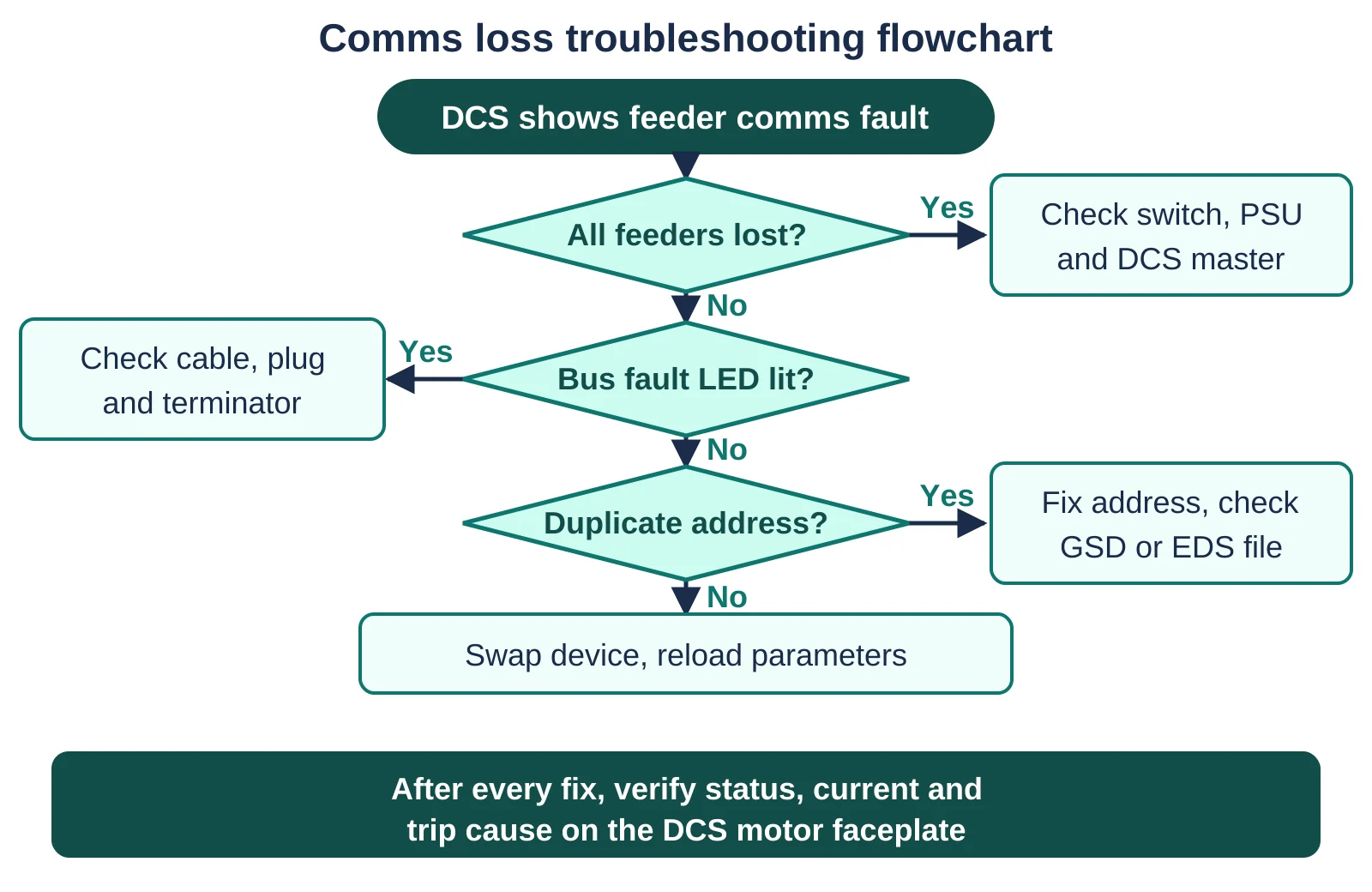
First check whether one feeder or all feeders are lost, because that shows whether the fault is at the device or at the switch, master or controller. Then check device LEDs, cable, termination and addressing in that order.
| Symptom | Likely cause | Fix |
|---|---|---|
| All feeders lost | Switch power or master card | Check 24 V supply and link LEDs |
| One feeder lost | Loose plug or damaged cable | Reseat plug, test cable |
| Random Profibus dropouts | Wrong termination | Terminate both segment ends only |
| Lost after replacement | Address not set | Set address or use init module |
| Current reads zero | Wrong mapping or CT ratio | Check byte map and CT settings |
Siemens offers an initialization module that automatically configures a replacement SIMOCODE device. Fit one per bucket so a technician can swap a relay without a laptop.
For Modbus panels, our Modbus RTU troubleshooting guide covers polling, parity and address conflicts. An industrial protocol gateway links mixed vendors, but keep a spare because it is a single point of failure.
Feeders can be direct on line or star delta, and our DOL vs star delta comparison helps you choose. Drive feeders behave like any variable frequency drive with a comms card added.
This Eaton video shows an intelligent MCC being built and tested in the factory. Eaton says factory setting of IP addresses and protection values shortens site commissioning.
A relay that accepts a remote start can also accept a malicious one, so plan segmentation and passwords early. For more on networks, read our page on PLC communication protocols.
Intelligent MCC FAQ
An intelligent MCC, or iMCC, is a motor control centre where every feeder uses a smart relay, drive or meter on a network. It sends status, current, thermal capacity and trip cause to the DCS without hardwired signals.
Busbars and buckets stay the same.
A conventional MCC sends each motor signal over a wired pair, while an iMCC sends them all over one network drop. For 40 motors with 7 signals each, the conventional panel needs 280 IO points and 560 cores.
The smart panel needs 40 network drops.
Multiply the number of motors by DI plus DO plus AI per motor. For 40 motors with 4 DI, 2 DO and 1 AI, the answer is 280 points.
Double the points to get cable cores, which gives 560 cores here.
The best protocol is the one your DCS supports natively, usually Profibus DP or Profinet for Siemens and EtherNet/IP for Rockwell. Modbus TCP suits mixed vendor plants.
Avoid gateways where possible, because each one adds configuration work and a failure point.
A single feeder usually drops because of a loose plug, damaged cable, wrong address or failed device. Check the device LED first, then cable and terminator.
If all feeders drop together, check the switch, its 24 V supply or the master card.
Yes, overload, phase failure and earth fault logic run inside the relay, so protection continues. You can also set most relays to stop or keep running on comms loss.
Choose that comms loss action for each motor based on the process risk.
Related Articles
- Motor Control Center (MCC) Explained
- Motor Protection Relay Types
- Profibus vs Profinet
- Thermal Overload Relay Explained
- VFD Sizing and Selection Guide
External References
- Siemens: Smart MCC Network Communications Manual (PDF)
- Eaton: Intelligent Motor Control Center Fundamentals
- Wikipedia: Motor control center
What We Learn Today
- An intelligent MCC keeps the normal power section but uses smart relays, drives and meters that report status, current and trip cause over a network.
- The IO saving equals motors times signals per motor, so 40 motors with 7 signals each remove 280 points and 560 control cable cores.
- Comms loss is found by checking whether one or all feeders dropped, then device LEDs, cables, terminators and addresses in that order.