
Most shutdown systems keep every input, relay and solenoid powered while the plant runs, so a broken wire or lost supply drives the process to its safe state. A few systems, such as deluge and fire suppression, do the opposite and need power to act.
A safety instrumented system can be designed so that loss of power causes a trip, or so that power is needed to cause a trip. This guide explains both philosophies, where each one belongs and how to protect the weaker one with line monitoring.
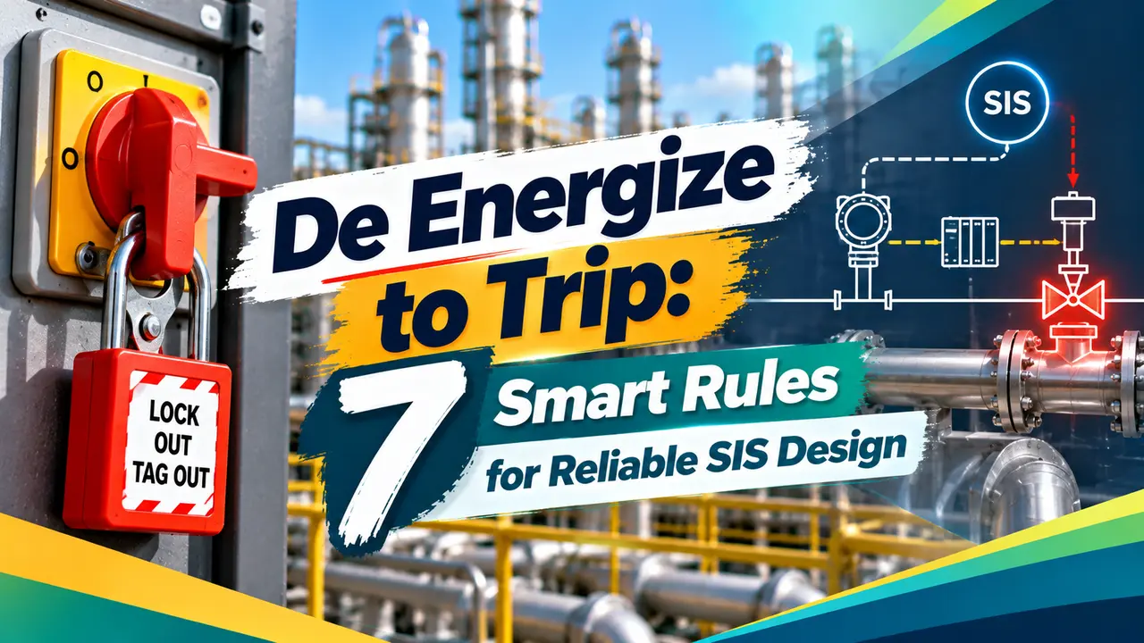
What Is De Energize to Trip?
De energize to trip is a design philosophy in which every element of a safety loop is kept powered during normal operation, and the safe action happens when that power is removed. It is the normal choice for an emergency shutdown system because a cut cable, a blown fuse or a failed power supply all lead to the same safe result.
In a typical loop the logic solver output holds a solenoid energized, the solenoid keeps instrument air on the actuator, and a spring holds the valve ready to close. When the output drops, the air vents and the spring drives the valve to the fail safe position without needing any outside energy.

The opposite approach, energize to trip, applies power to the final element only when a trip is demanded. It is less common, but it is the correct answer for systems where an unwanted action can itself hurt people or damage the plant.
How a Normally Energized Loop Holds the Plant Running
Rockwell Automation states plainly in its Logix safety documentation that its safety controller is part of a de energize to trip system. All of its outputs are set to zero when a fault is detected, which is the same idea that governs a hardwired safety relay.
The same principle extends to the sensor side. A transmitter can be configured so that a failure drives its current toward the trip value, using the downscale or upscale alarm levels defined in NAMUR NE43.
IEC 61511 uses the words energize and de energize for any motive force, not only electricity. Kenexis notes that pneumatic air pressure holding a valve open counts as energy in exactly the same way.
Energize to Trip: When Power Must Cause the Action
In an energize to trip loop the field device sits unpowered during normal operation, and the logic solver applies power only when a trip is needed. Loss of power or a broken wire therefore causes no action at all, which is a dangerous failure unless it is detected.
Outputs and sensors stay powered in normal operation and removal of energy moves the process to its safe state.
Final element stays unpowered and the logic applies energy to act, so circuits need supervision.
Sensors and logic are normally energized while one final element or one output group is energize to act.
A fire and gas system is the classic case. A spurious deluge floods electrical equipment, a false CO2 release endangers anyone in the room, and a false halt of fire pumps would be worse than useless.
De Energize to Trip vs Energize to Trip Compared
| Factor | De energize to trip | Energize to trip |
|---|---|---|
| Wire break | Causes a trip, safe | No action, dangerous unless monitored |
| Loss of power | Causes a trip | Function lost unless backup power exists |
| Spurious trips | Higher, every fault trips | Lower, faults do not act |
| Diagnostics needed | Basic | Line monitoring and power alarms |
| Typical users | ESD, BMS, machine safety | Deluge, suppression, some F and G outputs |
Line Monitoring With End of Line Resistors
Because an energize to trip circuit is idle most of the time, the logic solver must prove that the wiring is intact while nothing is happening. The usual method is to pass a small supervision current through the field circuit and watch for changes.
A resistor placed across the field contact at the last device, the end of line resistor, lets a small current flow even when the contact is open. A series resistor in the contact branch limits the current when the contact closes, so open wire, healthy idle, active and short circuit all give different currents.
The website Control and Instrumentation notes that there is no standard end of line resistor value, since each manufacturer and sometimes each input card sets its own. It also stresses that the resistor belongs at the last field device, never inside the control panel, or the cable itself is not supervised.
Contact closed current: I active = V ÷ (Rp × Rs ÷ (Rp + Rs))
Rp is the end of line resistor across the contact, Rs is the series resistor
R in kΩ gives current directly in mA
Example:
V = 24 V, Rp = 10 kΩ, Rs = 4.7 kΩ
I idle = 24 ÷ 10 = 2.40 mA
Rp parallel Rs = 47 ÷ 14.7 = 3.197 kΩ
I active = 24 ÷ 3.197 = 7.51 mA
An open wire gives close to zero current and a short circuit gives a current far above the active value. The input card sets alarm bands between these levels, which is the same idea used in a NAMUR output sensor.
Supervision Current Calculator
Second Worked Example: A Lower Current Supervision Loop
Suppose a card vendor specifies Rp = 22 kΩ and Rs = 2.2 kΩ on the same 24 V supply. The idle current is 24 ÷ 22 = 1.09 mA, and the parallel value is 22 × 2.2 ÷ 24.2 = 2.0 kΩ.
The contact closed current is therefore 24 ÷ 2.0 = 12.0 mA, a wide gap from the idle value that the card can separate easily. Always confirm the alarm thresholds in the card manual, because cable resistance and leakage on long runs shift these values slightly.
During loop checks, lift one wire at the last junction box and confirm the open circuit alarm, then short the pair and confirm the short circuit alarm. Record both results on the loop sheet before signing the circuit off.
7 Smart Rules for Choosing the Trip Mode
What IEC 61511 Asks For
Kenexis explains that clause 10 of IEC 61511 requires the safety requirements specification to state whether each SIS device is de energize to trip or energize to trip. For energize to trip, subclause 11.2.11 lists three attributes: alarm on loss of power, detection of circuit integrity faults, and a backup supply.
Kenexis adds that the backup supply is no longer strictly mandatory from the 2016 edition, though it is still recommended. In Indian refineries these choices sit alongside OISD guidance, and the SIL target from safety integrity level studies drives the architecture.
A 4 Sight Consulting paper published by the IET lists typical relay failure modes as about 80 percent open circuit contacts, 10 percent short circuit contacts and 10 percent coil faults. Since most relay faults open the circuit, a normally energized design turns the most common failure into a safe trip.
The same 4 Sight Consulting paper notes that some systems sold as normally energized designs still contain energize to act elements. A reset circuit or a latching solenoid can quietly need power to complete the safe action.
Spurious Trips and How to Reduce Them
The price of de energize to trip is that every fault, including a loose terminal, trips the plant. Voting is the main cure, and voting architectures such as 2oo3 keep the plant running when one channel fails.
Power supply design is the second cure, using redundant power supplies fed from separate sources and a UPS for the safety controller. On the final element side, two solenoids in a 2oo2 arrangement can stop a single coil failure from closing a valve.
Before blaming the logic for a spurious trip, read the first out alarm and the safety PLC diagnostics. Loose terminals in marshalling cabinets and tired solenoid coils cause many nuisance trips.
- Wire breaks and power loss lead to a safe state.
- Most relay and cable faults are revealed by a trip.
- Simple wiring and fewer diagnostics needed.
- Every fault trips the process, costing production.
- Coils run hot continuously and age faster.
- Power dips can cause unwanted shutdowns.
Where Each Trip Philosophy Is Used
Final elements decide most of the real world performance, so read SIS final element reliability alongside this article. Partial stroke testing of ESD valves helps reveal a stuck valve between full proof tests.
Commissioning Checklist for Trip Circuits
- Confirm the trip mode of every tag against the SRS.
- Remove loop power and verify the expected trip.
- Break each field wire and confirm the trip or the open circuit alarm.
- Short supervised pairs and confirm the short circuit alarm.
- Verify transmitter failure direction and NE43 alarm levels.
- Time the valve stroke and record it as a baseline.
Energise to Trip Guidance Paper
Fail Safe System Design Video
De Energize to Trip FAQ
It means every element of the safety loop is powered during normal operation. The safe action happens when that power or air is removed.
A broken wire, blown fuse or lost supply therefore leads to the same safe result as a real demand. This is why most shutdown systems in process plants use this approach.
It is used where an unwanted action could itself be dangerous or very costly. Deluge valves, clean agent release and fire pump starts in fire protection systems are common examples.
The final element sits unpowered and the logic applies energy only on demand. Such loops need line monitoring, power alarms and usually a backup supply to stay credible.
A broken wire in such a circuit causes no action and gives no sign of trouble. The fault stays hidden until a real fire or demand arrives.
An end of line resistor lets a small current flow at all times so the card can see the wiring. Open circuits and short circuits then raise alarms long before they matter.
Yes, the standard allows it when specific extra requirements are met. Kenexis lists alarm on loss of power, circuit integrity detection and a backup supply as the three attributes.
The backup supply is recommended rather than strictly required since the 2016 edition. The chosen trip mode for every device must also be written into the safety requirements specification.
Every fault in the loop, from a loose terminal to a power dip, produces a trip. That is safe but it costs production and erodes trust in the system.
Voting such as 2oo3, redundant power supplies and good terminations reduce these spurious trips greatly. Healthy solenoid coils and clean instrument air also help a lot.
No, fail safe simply means the valve goes to the position decided by the hazard study. For a feed valve that is usually closed, but for a blowdown valve it is usually open.
The actuator spring direction must match that decision. Always check the fail position on the valve datasheet and confirm it during loop commissioning.
A transmitter should fail in the direction that causes a trip wherever the process allows it. Low level trips usually use downscale failure and high pressure trips usually use upscale failure.
This setting extends the de energize to trip idea to the sensor side. The NAMUR NE43 alarm currents make such failures easy for the logic solver to detect.
Related Articles
- Emergency Shutdown System ESD
- Fire and Gas System in Process Plants
- Fail Safe Valve Position Explained
- Voting Architectures in Safety Systems
- Safety Instrumented Function Design
External References
- Energise to Trip? De Energise to Trip? Simple Choice? 4 Sight Consulting, IET
- Safety Requirements Specifications: Energize to Trip Requirements, Kenexis
- Safety Instrumented System, Wikipedia
What We Learn Today
- In a de energize to trip loop every input, output and solenoid stays powered, so wire breaks and power loss drive the process to its safe state.
- Energize to trip suits deluge and suppression systems where a spurious action is harmful, but it needs line monitoring, power alarms and backup supply.
- An end of line resistor across the field contact lets the card tell open wire, healthy idle, active and short circuit states apart by current.
