
A cracked fan blade or a loose bolt can shake a machine apart in minutes, long before anyone walks past it. A simple trip device mounted on the bearing housing can sense that shaking and stop the motor automatically.
Rotating machines always vibrate a little, but a sudden rise signals imbalance, looseness or failure. Trip devices compare the vibration level with a set point and open a contact to alarm or shut down the drive.

What Is a Vibration Switch?
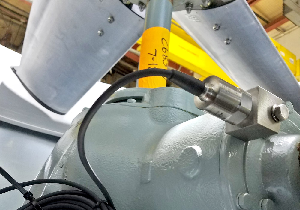
A vibration switch is a protective device mounted on a machine that changes a contact state when vibration exceeds a set level. It is simpler than the continuous monitoring covered in vibration sensor working, but it acts directly to alarm or trip.
A vibration switch is widely fitted to cooling tower fans, pumps, blowers, compressors and motors where a sudden failure could cause severe damage. The contact usually opens the motor starter circuit or signals a PLC.
Mechanical Inertia Switches
A mechanical vibration switch holds an armature in place with a magnet or spring latch. A strong enough acceleration overcomes the holding force, the armature moves and a snap action contact trips and stays latched.
SPX Cooling Tech states that mechanical switches cover about 0 to 60 Hz with amplitude ranges up to 16 g peak. They cost roughly one fifth of electronic units, but they are the least accurate option.
Reset of a latched vibration switch is manual, either by a button on the housing or a remote reset coil. The contact behaves much like a limit switch, but it is triggered by force rather than position.
Electronic Switches with Accelerometers
An electronic vibration switch uses a sensor, usually a piezoelectric or MEMS accelerometer, integrates the signal to velocity and compares it with a set point. The output is a relay or a solid state contact, of the kind listed in types of electronic switches.
SPX notes that an electronic vibration switch measures velocity from about 2 to 1000 Hz and often provide a 4 to 20 mA output. Smart versions sit in hermetically sealed stainless housings rated NEMA 4X or IP68.
The PCB Piezotronics white paper explains that electronic units support start up delays and alarm delays that mechanical types cannot offer. It adds that potentiometer set points carry uncertainty of 10 percent or more, while programmable units set thresholds precisely.
Velocity RMS and ISO Zones
Machine condition is judged mainly by broadband vibration velocity in mm/s RMS measured on bearing housings. ISO 10816 part 3, now revised as ISO 20816 part 3, groups industrial machines and defines zones A to D.
| Zone | Group 2 Rigid, mm/s RMS | Group 1 Rigid, mm/s RMS | Meaning |
|---|---|---|---|
| A | Up to 1.4 | Up to 2.3 | New machine condition |
| B | 1.4 to 2.8 | 2.3 to 4.5 | Acceptable for long running |
| C | 2.8 to 4.5 | 4.5 to 7.1 | Alarm, plan repair |
| D | Above 4.5 | Above 7.1 | Damage likely, trip |
Group 2 covers machines from 15 to 300 kW and Group 1 covers machines above 300 kW. Flexible foundations have higher limits, so always confirm the table for your machine type.
Converting g to mm/s
Velocity RMS = v peak × 0.707
Valid for a single sinusoidal frequency
Example:
a = 0.1 g peak = 0.981 m/s², f = 50 Hz
v peak = 0.981 ÷ 314.16 = 0.00312 m/s = 3.12 mm/s
v RMS = 3.12 × 0.707 = 2.21 mm/s
Zone B for Group 2 rigid, acceptable
At low speeds a small acceleration corresponds to a large velocity, which is why slow cooling tower fans need sensitive velocity measurement. The same acceleration at a higher frequency gives a much lower velocity.
Acceleration to Velocity Calculator
6 Vital Tips for Setting a Vibration Switch
Set the alarm above the running baseline and the trip near the zone C to D boundary. Wire the trip through the starter or a safety relay, alongside the thermal and overload functions described in motor protection relay types.
Cooling Towers, Pumps and Motors
PCB Piezotronics notes that electronic switches can detect fan imbalance per CTI Standard 163 at accelerations as low as 0.001 g at 70 RPM. A mechanical vibration switch lacks the inertial force to react to such pure imbalance.
Pump vibration patterns differ between the designs compared in centrifugal vs positive displacement pump. Motor related frequencies are easier to interpret once you know how an AC induction motor works.
- Direct protection with no controller needed.
- Low cost compared with full monitoring.
- Simple to install and wire.
- Electronic units offer delays and 4 to 20 mA.
- No diagnosis of the fault type.
- Mechanical units are coarse and unrepeatable.
- Poor mounting gives false readings.
- Needs regular trip testing.
A trip device only says that something is wrong. Trend data and spectra for predictive maintenance and AI based vibration analysis explain why.
PCB Piezotronics White Paper PDF
Field Testing Video
Vibration Switch FAQ
It watches the vibration level of a machine and changes a contact when a set point is exceeded. The contact can raise an alarm in the control room or stop the drive directly.
It protects fans, pumps and motors from severe damage after sudden mechanical faults. It is also simpler and cheaper than a full online monitoring system.
A magnet or spring holds an armature in a latched position inside the housing. A strong enough shock overcomes that holding force and snaps the contact open.
The switch then stays tripped until someone resets it by hand or remotely. Sensitivity is set by adjusting the holding force with a screw on the unit.
Velocity relates well to the energy and damage potential of vibration across common machine speeds. ISO machine vibration standards are therefore written in mm/s RMS.
Acceleration favours high frequencies, while displacement favours very low ones. Velocity gives a balanced view for general machinery running from about 10 to 1000 Hz.
They grade vibration severity from new machine condition up to likely damage. Zone B is acceptable for long running, while zone C needs attention and planned repair.
Zone D means damage is likely and the machine should be stopped. The exact limits depend on machine size, power and the type of foundation.
Machines often vibrate strongly for a few seconds while accelerating through resonance. Without a delay, the switch could trip the drive on every single start.
Electronic switches suppress the trip for a set time after the motor starts. An additional alarm delay also ignores short knocks and electrical transients.
Mount it rigidly on the bearing housing closest to the most likely fault. Avoid guards, thin sheet metal covers and flexible brackets that resonate on their own.
Align its sensitive axis with the direction of highest vibration on that machine. For most fans this direction is horizontal and perpendicular to the shaft.
Mechanical switches are low cost and need no power supply, but their set points are coarse. They suit simple shock protection on less critical equipment such as small fans.
Electronic switches give accurate velocity set points, start delays and analogue outputs. Choose them for critical pumps, large motors and slow cooling tower fans.
Related Articles
- Vibration Sensor Working
- MEMS Accelerometer Working Principle
- Predictive vs Preventive Maintenance
- Motor Protection Relay Types
- Centrifugal vs Positive Displacement Pump
External References
- Vibration Switch White Paper, PCB Piezotronics
- Cooling Tower Switch Options, SPX Cooling Tech
- Condition Monitoring, Wikipedia
What We Learn Today
- A vibration switch trips an alarm or motor when vibration exceeds a set point, using either a mechanical latch or an electronic accelerometer.
- Velocity in mm/s RMS is compared with ISO 10816 or ISO 20816 zones, and acceleration converts to velocity by dividing by 2πf.
- Rigid mounting, the correct sensing axis, start up delays and regular trip tests make protection on fans, pumps and motors truly dependable.