
A SIL 2 certified transmitter doesn't make a SIL 2 safety loop. The architecture around it does.
Get the voting logic wrong and a system built entirely from "certified" parts can still fail exactly when it's needed.
Safety instrumented function (SIF) design means choosing a sensor, logic solver, and final element architecture that achieves a target SIL by balancing dangerous failure probability against unwanted spurious trips.
Every SIF is built from three subsystems: a sensor, a logic solver, and a final element. Each one can use a different voting architecture.
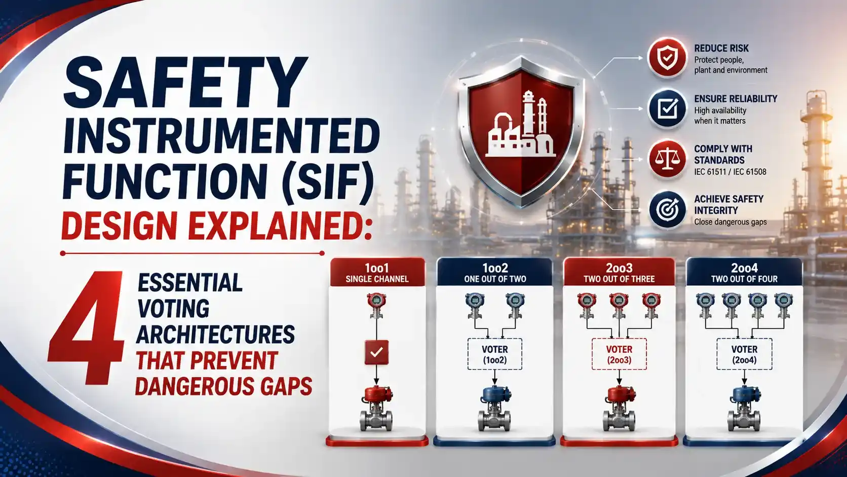
Get the voting architecture right, and the loop hits its SIL target with an acceptable nuisance trip rate. Get it wrong, and the certificate on the transmitter means nothing.
The 4 Core Voting Architectures in SIF Design
Architecture is always written as MooN, meaning M channels out of N total must agree before acting.
One Channel, No Redundancy
Simplest and cheapest, but a single dangerous failure blinds the entire safety function. Limited to lower SIL targets.
Trip on Either Channel
Two channels, either can trigger a trip. Excellent safety, since one channel covers the other's failure, but higher spurious trip rate.
Both Channels Must Agree
Reduces nuisance trips, but a single undetected dangerous failure quietly turns this into an unprotected 1oo1 system.
Majority Voting
Two of three channels must agree. Strong safety and low spurious trips together, the most common choice for critical SIFs.
Trip on OR vs Trip on AND
Every voting architecture reduces to one of two basic logic philosophies.
Trip on OR (1oo2)
Any single channel detecting a hazard trips the system. "When in doubt, shut it down" philosophy.
Trip on AND (2oo2)
Both channels must agree before tripping. Fewer unnecessary shutdowns, but a hidden single failure defeats it.
The 3 Subsystems of Every SIF
A safety instrumented function is never just one device. It's a chain of three subsystems, and each one can carry its own architecture.
The overall SIF reliability is the product of all three subsystem reliabilities. A brilliant 2oo3 sensor architecture is wasted if the final element is a single, poorly maintained valve.
PFDavg Formulas for 1oo1 and 1oo2
These simplified formulas from IEC 61508 show how architecture and testing frequency directly control the result.
TI = proof test interval (hours)
Example: λDU = 5e-7/hr, TI = 8760 hours (1 year)
PFDavg = 5e-7 x 8760 / 2 = 0.00219
Example: λDU = 5e-7/hr, TI = 8760 hours, β = 0.05
Independent term = (5e-7 x 8760)^2 / 3 = 0.0000032
CCF term = 0.05 x 5e-7 x 8760 / 2 = 0.0001095
PFDavg = approximately 0.000113
Voting Architecture Comparison
Here's how the four architectures stack up on safety, availability, and typical SIL capability.
| Architecture | Safety (PFDavg) | Spurious Trip Rate | Typical Max SIL |
|---|---|---|---|
| 1oo1 | Baseline | Low | SIL 1 to SIL 2 |
| 1oo2 | Much better than 1oo1 | High | SIL 2 to SIL 3 |
| 2oo2 | No better than 1oo1 | Very low | Not recommended for high SIL |
| 2oo3 | Better than 1oo1, close to 1oo2 | Low, close to 1oo1 | SIL 2 to SIL 3 |
Typical Beta Factor Values by Subsystem
Common cause failure fraction varies by which part of the SIF is being analyzed.
| Subsystem | Typical Beta Factor |
|---|---|
| Sensor (transmitters) | 5% |
| Logic Solver | 2% |
| Final Element (valves, actuators) | 10% |
Where SIF Voting Architectures Are Used
Fired Heater Shutdown
2oo3 pressure or flow trip on critical burner management systems.
Reactor Overpressure
High integrity pressure protection using redundant sensor voting.
Emergency Shutdown (ESD)
1oo2 or 2oo3 architectures on plant-wide ESD trip functions.
Compressor Trip Systems
Redundant vibration and temperature sensing on rotating equipment.
Power Plant Protection
Turbine overspeed trip logic using triple modular redundancy.
Level Protection Loops
High-high level SIFs preventing tank or vessel overfill.
Hardware Fault Tolerance and Architectural Constraints
PFDavg math isn't the only requirement. IEC 61511 also imposes architectural constraints based on Hardware Fault Tolerance, or HFT.
HFT is the number of channels that can fail while the SIF still performs its safety function. A 1oo1 system has HFT of 0. A 1oo2 or 2oo3 system has HFT of 1.
Depending on the device's Safe Failure Fraction and the target SIL, a route may require minimum HFT regardless of how good the calculated PFDavg looks on paper. This is exactly why a certified SIL 3 transmitter still can't be used alone in a 1oo1 configuration for every SIL 3 application.
Do's and Don'ts of SIF Design
✓ Do
- Calculate PFDavg for the whole SIF, not just one device
- Use diverse sensor types where possible to lower common cause risk
- Match proof test interval to the actual SIL target, not a default value
- Document architectural constraints alongside the PFDavg calculation
✗ Don't
- Assume a SIL 3 certified transmitter makes a SIL 3 loop by itself
- Default to 2oo2 voting for a high SIL target
- Ignore the beta factor when calculating redundant architectures
- Forget that final elements often carry the highest beta factor of the three subsystems
Live SIF PFDavg Calculator
Select an architecture and enter failure rate, test interval, and beta factor to estimate PFDavg.
Reference Materials on SIF Design
FAQs on Safety Instrumented Function (SIF) Design
External References
- Architecture for SIFs (1oo1, 1oo2), SIL Safe
- Functional Safety Architectures: 1oo1 vs 1oo2 vs 2oo2 vs 2oo3, InstruNexus
- Usual Architectures in a Safety Instrumented Function, Enertria
- Safety Instrumented Function Verification: The Three Barriers, exida
- PFD Formulas in IEC 61508, NTNU
What we learn today
- Safety instrumented function (SIF) design comes down to choosing the right voting architecture: 1oo1, 1oo2, 2oo2, or 2oo3.
- 1oo2 trips on either channel, favoring safety, while 2oo2 requires both channels to agree, favoring availability over safety.
- 2oo3 majority voting balances both, achieving strong safety performance with a low spurious trip rate.
- PFDavg for 1oo1 is lambda DU times test interval divided by 2, while 1oo2 adds an independent failure term and a common cause (beta factor) term.
- A SIF's overall reliability is the product of its sensor, logic solver, and final element subsystems, not just the rating of one certified device.