
Most large tank fires in the last few decades began with something as ordinary as a tank receiving more product than it could hold. Clear alarm levels, an independent sensor and a tested shutdown path turn that ordinary mistake into a non event.
API 2350 gives terminal and refinery owners a structured approach to overfill protection for storage tanks. This guide explains the levels of concern, tank categories, response time calculation and how Indian terminals apply the same ideas.
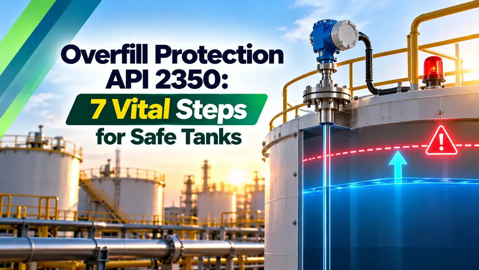
What Is Tank Overfill Protection?
Tank overfill protection is the combination of level instruments, alarms, procedures and shutdown devices that stops product transfer into a storage tank before the liquid reaches a level where it can spill or damage the tank. In petroleum terminals it normally sits on top of the automatic tank gauging system used for inventory.
API 2350, Overfill Prevention for Storage Tanks in Petroleum Facilities, is the main international standard for this job. Its first edition appeared in March 1987, and the current fifth edition includes lessons from the 2005 Buncefield depot fire in the United Kingdom.

The tanks above belong to an Endress+Hauser case study in which a Middle East operator added independent high level alarms using SIL 3 vibrating fork switches, because its API 2350 based standard demanded a sensor separate from the tank gauge. The working principle of those switches is covered in vibrating fork level switch.
Why Overfill Protection Matters
A Hydrocarbon Engineering article on HPCL notes that overfilling was the most frequently attributed cause among more than 240 recorded storage tank accidents over 40 years. Overfilling a tank of flammable liquid without working overfill protection creates a vapour cloud that only needs an ignition source.
The US Chemical Safety Board investigated the October 2009 Caribbean Petroleum explosion, where tank 409 overflowed during a gasoline receipt. The vapour cloud covered about 107 acres and the blast damaged roughly 300 nearby homes and businesses.
The CSB found that the transmitter card for the tank gauge was out of service and the site relied on a float and tape gauge, with no independent high level alarm and no automatic shutdown. These are exactly the missing layers that layer of protection analysis is designed to reveal.
The Jaipur depot fire of the same month, October 2009, killed 12 people and forced the evacuation of about 500,000 residents, according to Hydrocarbon Engineering. Its inquiry, the M B Lal Committee, reshaped tank farm safety rules across India.
Overfill Protection Levels of Concern in API 2350
API 2350 asks every tank to have defined levels of concern, measured from the tank bottom. They are fixed from tank geometry first and then adjusted for the time operators need to react.
Highest level before overflow or damage to the tank or floating roof.
Point where an automatic system closes the inlet, at or above HH.
The only alarm the standard requires, set below CH by the response time.
Highest level for routine filling, with an optional alert.
Emerson notes that the fifth edition requires a minimum safety margin of 75 mm, about 3 inches, between two levels of concern such as CH and HH. The margin covers instrument error and level rise while signals are processed.
Tank Categories and Default Response Times
| Category | Typical Setup | Default Minimum Response Time |
|---|---|---|
| 0 | Manual hand gauging, fully attended | 60 minutes |
| 1 | Local level reading, operator on site | 45 minutes |
| 2 | Level and alarm sent to a control centre from the ATG | 30 minutes |
| 3 | As category 2 plus an independent high level alarm | 15 minutes |
Inspenet summarises the fifth edition categories and their default response times as 60, 45, 30 and 15 minutes for categories 0 to 3. Category 0, for tanks with manual hand gauging only, is new in the fifth edition.
Owners may calculate a tank specific response time instead of using the defaults, but it must be documented. Category 3 is the recommended setup and needs at least one automatic tank gauge and one independent overfill protection sensor, kept separate from the basic process control system.
Write the category, response time and every level of concern on the tank datasheet and the DCS faceplate. Operators should never have to look up a number in a binder while a receipt is running.
Response Time and HH Level Formula
The response time is the time operators need, after the HH alarm, to recognise the alarm and stop the receipt before the level reaches CH. The HH level must therefore sit at least one response time of level rise below CH.
HH distance below CH = Rise rate × Response time, minimum 75 mm
Example, category 2 tank:
Diameter 30 m, area = π × 30² ÷ 4 = 706.86 m²
Receipt 1000 m³/h, response time 30 minutes, CH = 14000 mm
Rise = 1000 ÷ 706.86 × 1000 ÷ 60 = 23.58 mm/min
Distance = 23.58 × 30 = 707 mm
HH at or below 14000 minus 707 = 13293 mm
Use the highest receipt rate the tank can see, usually a ship or pipeline batch rather than a road tanker. Cross check the area against the strapping table, since internal structures and floating roofs change the effective area, and make sure a servo level gauge or radar gauge uses the same datum.
Overfill Protection Calculator
Second Worked Example: Small Category 1 Tank
A 12 m diameter diesel tank at a depot has an area of 113.10 m² and receives up to 200 m³/h from a pipeline. The rise rate is 200 ÷ 113.10 × 1000 ÷ 60 = 29.47 mm/min, faster than the large tank because the area is much smaller.
As a category 1 tank it uses the 45 minute default, so the HH distance is 29.47 × 45 = 1326 mm. With CH at 9000 mm, HH goes at or below 7674 mm, which costs a lot of usable volume and is a strong argument for upgrading to category 3 with its 15 minute default.
Manual vs Automatic Overfill Protection
- HH alarm prompts an operator to act.
- Operator closes a valve locally or from the control room.
- Lower cost and simpler to install.
- Depends on alarm response and staffing.
- Sensor and logic solver close the inlet directly.
- No reliance on operator reaction time.
- Must be independent of the BPCS.
- Needs SIL design, proof testing and bypass control.
Inspenet notes that when an AOPS is installed its activation level must be at or above HH and that new automatic systems should follow IEC 61511. In practice that means a safety instrumented function with a defined SIL, a logic solver and a final element, usually a fail closed inlet valve.
The final element needs a closing time short enough to fit inside the response window and slow enough to avoid surge in the pipeline. Valve testing methods such as partial stroke testing of ESD valves help prove that it will move when called.
API 2350 is not only about instruments. It also asks for a management system, written procedures and a risk assessment for each tank, so a perfect sensor without trained operators is still non compliant.
Choosing Independent Overfill Protection Sensors
An independent overfill protection sensor must not share the transmitter, cable, power or logic of the inventory gauge. Common choices are point level switches and a second, safety rated radar level transmitter that gives continuous readings and an alarm.
For a structured comparison of switch technologies, see level switch selection.
Mount the independent overfill protection switch at the HH or AOPS level, not at CH, so it alarms with the full response time still available. A switch at CH only tells you the tank is already in trouble.
7 Vital Steps to Implement API 2350
Proof testing is where many sites fall short. Emerson notes that every component involved in stopping a receipt must be proof tested at least annually unless a calculation justifies another interval, a topic explained in proof test interval and coverage.
Overfill Protection in Indian Terminals
In India, oil depots and terminals follow OISD STD 244 on storage and handling of petroleum products, a standard revised with new guidelines in the years after the Jaipur fire. Hydrocarbon Engineering describes how HPCL adopted the committee recommendations.
HPCL built a SIL 2 safety interlock for close to 600 product tanks across 63 locations, with radar gauges and level switches as sensors, an ESD logic solver and remote operated shut off valves. This is a textbook automatic overfill protection loop, and its logic resembles the emergency shutdown system found in process plants.
Overfill Protection Commissioning Checklist
- Verify CH, HH, AOPS and MW against tank drawings and strapping tables.
- Confirm the overfill protection sensor shares no cable, power or logic with the ATG.
- Raise the level or simulate the switch and confirm the alarm reaches the operator.
- Time the full trip, from sensor to valve closed, against the response time.
- Check the valve closes fully and does not cause pipeline surge.
- Record bypasses and ensure they are time limited and authorised.
- Document results and repeat at least once a year.
Emerson Article on API 2350
CSB Safety Video on Tank Overfill
Overfill Protection FAQ
It is the set of instruments, alarms, procedures and shutdown devices that stop a receipt before a tank overflows. API 2350 is the main standard used for petroleum storage tanks.
It normally combines the tank gauge, an independent high level sensor and a way to close the inlet. Manual systems rely on an operator while automatic systems close the valve directly.
The critical high level is the highest point before overflow or damage. The high high level is the one alarm the standard requires, and it sits below critical high.
An automatic system level can be set at or above high high. The maximum working level is the highest level for routine filling and may carry an optional alert.
The response time is the time needed to recognise the high high alarm and stop the receipt. Multiplying it by the level rise rate gives the minimum gap between high high and critical high.
The fifth edition defaults are 60, 45, 30 and 15 minutes for categories 0 to 3. Sites may calculate their own value but must document it clearly.
It must not share the transmitter, cabling, power supply or logic with the inventory tank gauge. A single fault should never be able to disable both the inventory gauge and the overfill protection alarm.
Point level switches and separate safety rated radar gauges are the usual choices. Each needs its own route to the operator or logic solver.
API 2350 leaves the choice to the risk assessment, but automatic systems suit high consequence or unattended tanks in particular. They remove the dependence on operator reaction during fast ship or pipeline receipts.
An automatic system must be independent of the control system. New designs should follow IEC 61511 with a defined SIL and regular proof tests.
Emerson notes that every component involved in stopping a receipt must be proof tested at least once a year. A longer interval needs a documented technical justification such as a failure calculation.
Testing should cover the sensor, the logic and the valve together. Remote testable switches and safety radar gauges make this easier without lifting the tank level.
Indian oil depots follow OISD STD 244, which was revised with new guidelines after the Jaipur fire. Many companies also apply the M B Lal Committee recommendations and API 2350.
HPCL, for example, installed a SIL 2 interlock with radar gauges, level switches and remote shut off valves. It covers close to 600 tanks across 63 locations.
Related Articles
- Automatic Tank Gauging Explained
- Vibrating Fork Level Switch Working
- Safety Instrumented Function SIF Design
- Layer of Protection Analysis and SIL Assessment
- Emergency Shutdown System ESD
External References
- API 2350 and Reducing the Risk of Overfills, Emerson
- API 2350 for Tanks Overfill Prevention, Inspenet
- Storage Tank, Wikipedia
What We Learn Today
- API 2350 sets critical high, high high, optional AOPS and maximum working levels, with at least 75 mm between two levels of concern.
- The HH gap below CH equals the level rise rate times the response time, with defaults of 60, 45, 30 and 15 minutes.
- Reliable overfill protection needs an independent sensor, a tested shutdown path and annual proof tests, as Indian terminals now apply alongside OISD STD 244.
