
A servo gauge doesn't just hang a displacer in a tank and read a number.
It's a continuously self correcting weighing machine, chasing the liquid surface thousands of times a day to keep one small object exactly balanced.
A servo level gauge working principle relies on continuously rebalancing a small displacer against buoyant force, using a servo motor to track the liquid surface to within a fraction of a millimeter.
Picture a standard displacer level transmitter, but instead of hanging passively on a spring, the displacer rides on a wire. A motor actively winds that wire in and out.
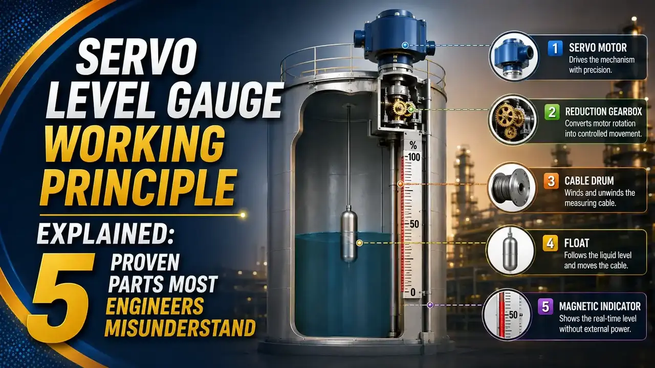
The gauge never lets the displacer drift out of balance for long. The instant buoyancy shifts, the motor repositions the displacer to restore the exact same reference weight.
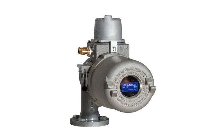
The 5 Core Parts of a Servo Level Gauge
Every servo gauge, regardless of brand, is built around the same five working parts.
Displacer
A small, dense object lowered into the liquid, denser than the process fluid so it never floats freely.
Measuring Wire and Drum
A fine stainless steel wire winds onto a precision grooved drum that tracks exact displacer position.
Magnetic Coupling
Outer magnets on the drum and inner magnets on the motor transfer torque without any shaft seal penetrating the housing.
Hall Effect Sensors
Typically five sensors detect tiny changes in magnetic flux as buoyancy shifts the torque on the coupling.
Servo Motor and Control Loop
Drives the drum to raise or lower the displacer, continuously restoring the reference apparent weight.
Servo Gauge vs Static Displacer Transmitter
Both rely on Archimedes' principle, but one sits still while the other actively hunts for balance.
Static Displacer (Torque Tube)
Stays at a fixed position, sensing a change in apparent weight as level moves past it. Simple, no moving control loop.
Servo Gauge
Actively repositions the displacer to stay exactly at the surface, using a closed control loop for extreme precision.
How Null-Balance Control Actually Works
Null-balance means the gauge always drives the error back to zero, rather than measuring a steady state deflection.
The wire position, not the displacer's weight reading, is what actually gets converted into the level measurement. Position is precise. Weight alone would drift with vibration and friction.
Buoyancy and Density Formulas
The same buoyant force math applies here, but a servo gauge can also solve it in reverse to determine liquid density.
ρ = ΔF / (g x A x Δh)
ΔF = change in apparent weight, Δh = change in immersion depth
Example: A = 0.0008 m2, ΔF = 0.04 N, Δh = 0.05 m
ρ = 0.04 / (9.81 x 0.0008 x 0.05) = approximately 1019 kg/m3
Servo Gauge vs Radar Gauge
Servo remains common in existing terminals, but radar is now the default choice for new installations.
| Property | Servo Gauge | Radar Gauge |
|---|---|---|
| Moving parts | Yes, wire, drum, motor, displacer | None in the measurement path |
| Typical accuracy | ±0.4 to 0.7 mm | Comparable or better, no wear-related drift |
| Density and interface measurement | Native capability | Requires added sensors or hybrid setup |
| Maintenance | Higher, mechanical wear over years | Lower, largely maintenance free |
Where Servo Level Gauges Are Used
Custody Transfer
OIML R85 and API 3.1B certified fiscal measurement.
Crude Oil Storage
Bulk terminal inventory management and reconciliation.
Interface Measurement
Oil-water interface tracking in separator and storage tanks.
Density Profiling
Measuring density at multiple depths in a stratified tank.
Refined Products
Light and middle distillate storage and blending operations.
Overfill Prevention
SIL 2/3 rated independent high level protection.
Why Wire Winding Layers Affect Accuracy
A grooved drum sounds simple, but multi-layer winding introduces a subtle error source engineers should know about.
As the wire builds up in layers, the effective drum radius changes slightly with each layer. The same motor rotation now represents a different length of wire feed.
High end servo gauges compensate for this electronically, tracking exactly which layer the wire sits on. Older or poorly maintained units can drift in accuracy specifically because this compensation degrades over time.
Do's and Don'ts of Servo Gauge Operation
✓ Do
- Inspect the measuring wire regularly for wear or corrosion
- Verify density readings against a lab sample periodically
- Keep the displacer clean, since sticky product can bias the weight reading
- Confirm magnetic coupling integrity during scheduled maintenance
✗ Don't
- Ignore repeated fault alarms on the servo motor drive
- Assume density accuracy matches level accuracy in every service
- Let foam or vapor buildup interfere with displacer contact detection
- Treat a servo gauge as maintenance free simply because it's precise
Live Liquid Density Calculator (Buoyancy Method)
Enter the displacer area, force change, and immersion depth change to calculate liquid density the way a servo gauge does internally.
Reference Materials on Servo Level Gauges
FAQs on Servo Level Gauge Working Principle
External References
- Servo Tank Gauges Working Principle, Inst Tools
- Common Tank Gauging Technologies and How They Work, Varec
- Servo Level Measurement, Endress+Hauser
- Servo vs Radar Whitepaper, Honeywell Enraf
- Rosemount Tank Gauging System Product Data Sheet, Emerson
What we learn today
- A servo level gauge working principle relies on 5 core parts: displacer, measuring wire and drum, magnetic coupling, Hall sensors, and a servo motor control loop.
- Null-balance control continuously drives the displacer back to a fixed reference apparent weight, and the precise wire position is what becomes the level reading.
- The same buoyancy formula used for static displacers also lets a servo gauge calculate liquid density from a known change in immersion depth.
- Servo gauges reach roughly plus or minus 0.4 to 0.7 millimeter accuracy, making them a long standing standard for custody transfer measurement.
- Radar has become the default for new installations due to fewer moving parts, but servo gauges remain valued for native density and interface measurement.