
A test is a scheduled, documented functional test of a SIS component that detects undetected dangerous failures and restores the component to a known good state.
test interval and test coverage directly determine the PFD avg of a safety transmitter — and therefore whether the SIF achieves its target SIL.
This guide explains the IEC 61511 proof test requirements, defines test coverage, shows how interval and coverage affect PFD avg, and includes a live PFD avg calculator for safety transmitters.
The single most powerful lever an operations team has on SIF performance is the proof test interval.
A SIF that fails its SIL target can often be brought into compliance by shortening this interval.
Equally, lengthening the test interval to reduce maintenance burden can push a previously compliant SIF above its PFD target. Understanding this mathematics is essential for anyone maintaining a safety-critical measurement.
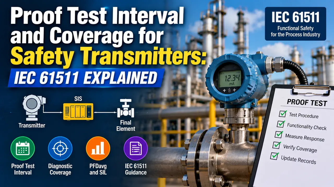
What Is a testing a safety transmitter?
A safety transmitter in a SIF loop can fail invisibly to the control room.
The output may appear healthy — a plausible process value, within range, no diagnostic alarm — while the sensor has failed and would not correctly indicate a hazardous condition.
This is called a dangerous undetected (DU) failure. The transmitter is in a failed state, but neither the logic solver nor the operator knows it.
The SIS would not respond correctly to a demand on the SIF until someone physically tests the transmitter and discovers the fault. The scheduled test exists to find these DU failures.
The 2016 edition of IEC 61511 added a specific requirement (Clause 16.2.5) that test procedures must be written, that the test must be capable of detecting the dangerous undetected failures assumed in the SIL verification calculation, and that the test results must be recorded and reviewed.
This means a test that simply verifies the transmitter reads a known value — but does not test the entire signal path from sensor tip to logic solver input — may not satisfy IEC 61511 even if it is performed at the correct interval.
How test interval Affects PFD avg: The Formula
For a single component in a 1oo1 (one-out-of-one) configuration, the simplified IEC 61511 PFD avg formula is:
Where:
λDU = dangerous undetected failure rate (per year), from the device FMEDA
Ti = test interval (years)
This formula assumes a perfect proof test (coverage = 100%). When test coverage (PTC) is less than 1.0:
PFD avg = PTC × (λDU × Ti / 2) + (1 - PTC) × λDU × TL / 2
Where:
PTC = test coverage (fraction of DU failures detected by the test)
TL = equipment useful life (typically 10 to 20 years for process transmitters)
The first term represents failures detected and restored by the test.
The second term represents failures that persist for the full useful life because the test misses them.
Suppose a pressure transmitter has λDU = 8.76×10⁻⁴ per year (1.0×10⁻⁴ per hour).
With a 1-year test interval and 100% coverage: PFD avg = 8.76×10⁻⁴ × 1 / 2 = 4.38×10⁻⁴ — within SIL 1.
Extending the test interval to 3 years: PFD avg = 8.76×10⁻⁴ × 3 / 2 = 1.31×10⁻³ — still SIL 1, but approaching the boundary.
At 12 years: PFD avg = 5.26×10⁻³ — approaching SIL 1's limit of 0.01. The test interval directly controls where the transmitter sits within its SIL band.
SIL verification reports are written before the plant is built, and they assume a specific test interval — often 1 year or 2 years for safety transmitters. That assumed interval is not automatically enforced on the plant; the maintenance schedule must be explicitly set to match it.
If the plant maintenance team decides to extend the test interval (for example, to align with a 4-year turnaround instead of an annual shutdown), the SIL verification calculation must be re-run to confirm the SIF still meets its PFD target at the new interval. Do not assume it still passes without checking the numbers.
Proof Test Coverage: What It Means and Why It Matters
Test coverage (PTC) is the fraction of dangerous undetected failures a test detects. A PTC of 0.9 means 10% of DU failures persist until the next test or until the equipment fails.
Coverage depends entirely on what the test actually does, not how long it takes or how often it is performed.
A test that checks only whether the output is within range has low coverage. It misses sensor drift, impulse line blockage, and many electronic failures that produce a plausible-looking output value.
For example, an Emerson Rosemount 3051 pressure transmitter FMEDA may quote PFD avg values assuming a "full proof test" that includes applying a known reference pressure to the transmitter and verifying the output matches within accuracy specification, checking all terminals, and testing the 4-20 mA output circuit continuity.
If your site's actual proof test procedure is less comprehensive than the manufacturer's assumed procedure, the published PFD avg value is not valid for your site. You must use a lower PTC value in your own PFD avg calculation, which will give a higher (worse) PFD avg than the data sheet implies.
test procedure for a safety transmitter: 5 Steps
Isolate and Bypass the SIF
Notify the SIS operator and control room before testing. Place the SIF in bypass mode in the logic solver. See the SIF design guide for bypass management requirements.
Record the bypass start time. Maximum bypass duration must be tracked against the plant's acceptable risk position for the bypassed SIF.
Test the Primary Element and Process Connection
For a pressure transmitter: blow down the impulse lines and verify flow, then close the isolating valves and confirm the transmitter reads the correct static pressure.
For a level transmitter: drain or flush the level pot. For a temperature element: inspect the thermowell for scaling and verify the RTD or thermocouple against a reference standard.
This step has the highest coverage value — it tests the complete measurement path from the process connection, not just the electronic output.
Apply a Reference Input and Verify Output
Apply a known reference input to the transmitter's sensing element and verify that the 4-20 mA output matches the expected value within calibration tolerance. Record the as-found reading before making any adjustments.
If the as-found reading differs by more than the allowed tolerance, this is a DU failure. Record it as a finding, restore the transmitter, and report it in the test record.
Verify the Complete Signal Path to the Logic Solver
Confirm that the 4-20 mA output reaches the logic solver input card and that the logic solver reads the expected value. Verify the SIS trip threshold is correctly configured.
This step catches signal path failures — broken wires, corroded terminals, failed input cards — that the transmitter alone cannot detect. Without this step, test coverage is significantly reduced.
Restore and Remove Bypass
Confirm all valves are restored to normal operating position and all test equipment is removed. Remove the bypass in the logic solver and confirm the SIF is active.
Record the bypass end time and the complete test result (as-found, as-left, findings) in the SIS maintenance management system.
IEC 61511 Clause 16 requires that test records are retained and reviewed at defined intervals. Any DU failures found must be analysed for pattern or common cause failure implications.
The as-found reading is the only objective evidence of whether the transmitter was in a DU failure state when you arrived. If you adjust the transmitter first and then record the final reading, you have lost the data that tells you whether the SIF was actually meeting its PFD target between tests.
As-found data, collected over multiple tests, is the basis for the test effectiveness review that IEC 61511-1 Clause 16.2.7 requires. It allows you to see whether failures are increasing with age, whether a particular failure mode is recurring, and whether the assumed PTC value in the SIL verification is realistic for your site.
Proof Test Coverage Values for Common Transmitter Test Types
| Proof Test Procedure | Typical PTC | Failures Detected / Missed |
|---|---|---|
| Visual inspection only (check for physical damage, verify transmitter is powered and reading) | 0.0 to 0.3 | Detects: severe physical damage, total loss of power. Misses: sensor drift, impulse line blockage, internal electronic faults, signal path faults. |
| Functional test at one point (verify output at current process conditions against DCS reading) | 0.3 to 0.5 | Detects: gross signal errors, obvious failures. Misses: drift at trip point, impulse line blockage at static conditions, common-cause failures with DCS sensor. |
| End-to-end signal path test (inject known mA signal at transmitter output and verify at logic solver) | 0.4 to 0.6 | Detects: wiring faults, input card faults, configuration errors. Misses: sensor element failures, primary element blockage. |
| Reference input test (apply known pressure/temp/level to sensor, verify 4-20 mA output matches) | 0.7 to 0.85 | Detects: sensor drift, sensing element faults, calibration shift. Misses: impulse line failures if lines not also tested, signal path faults if signal path not separately tested. |
| Full proof test (reference input + signal path + impulse line blowdown + trip threshold verification) | 0.9 to 0.99 | Detects: all major DU failure modes for pressure and level transmitters. Residual undetectable failures: internal PCB faults that produce in-range but incorrect output under specific process conditions only. |
| Full proof test with HART/digital diagnostic check (as above + review of HART diagnostic memory for logged events) | 0.95 to 0.99 | Adds coverage of intermittent and historical diagnostic faults that may not be active at test time. Best available PTC for smart transmitters. |
Safety Transmitter PFD avg Calculator
Watch: IEC 61511 Safety Lifecycle Overview (2024)
Proof Test Questions Engineers Ask
Related Articles on This Site
- What Is SIL? Safety Integrity Level Explained
- Safe Failure Fraction Explained in Functional Safety
- SIS Final Element Reliability: Why Valves Often Dominate SIF Performance
- Safety Instrumented Function (SIF) Design Explained
- What Is a Functional Safety Assessment?
External References
- ISA-84 / IEC 61511: Safety Instrumented Systems for the Process Industry Sector | ISA
- Proof Testing Basics for Safety Instrumented Systems | exida (2024)
What We Learn Today
- the test interval Ti and proof test coverage PTC together determine PFD avg for a safety transmitter. The simplified IEC 61511 formula is: PFD avg = PTC × (λDU × Ti / 2) + (1 minus PTC) × (λDU × TL / 2). Halving Ti approximately halves PFD avg. A test with low coverage leaves a residual PFD contribution that persists for the full equipment life regardless of how frequently the test is performed.
- A full proof test for a pressure transmitter covers five elements: isolate and bypass the SIF, test the impulse lines and primary connection, apply a reference input and verify output, verify the complete signal path to the logic solver, then restore and remove the bypass. Skipping any element — especially the impulse line test or the signal path verification — significantly reduces actual test coverage below the value assumed in the SIL verification report.
- IEC 61511 Clause 16 requires proof tests to be planned, documented, performed at the interval assumed in SIL verification, and the results reviewed. Any change to the test interval must be accompanied by a re-run of the SIL verification to confirm the SIF still meets its PFD target at the new interval.