
A temperature switch sits quietly for months and then must act at exactly the right moment to start a fan or trip a heater. A careful calibration proves the set point, the reset point and the contacts before the plant ever depends on them.
A temperature switch has no display to tell you it has drifted, so only a planned test reveals the problem. This temperature switch calibration guide covers equipment, ten field steps, deadband, tolerance checks and good records.
What Is Temperature Switch Calibration?
Temperature switch calibration is the process of finding the exact temperatures at which a switch changes its contact state, comparing them with the required values and adjusting or replacing the switch when they are out of tolerance. Unlike a temperature transmitter calibration, there is no continuous output to read, only a contact that opens or closes.
Every switch must be checked for two points: the set point, where the output changes as the temperature moves in the active direction, and the reset point, where it returns to normal. The difference between them is the deadband, which is also called hysteresis.
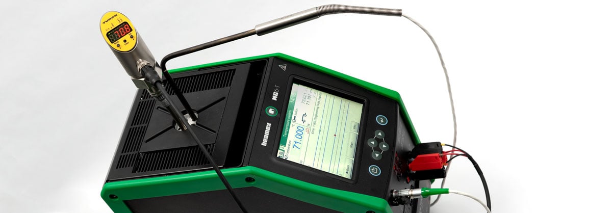
Beamex explains the idea with a room radiator set to 20 °C that switches on below 19 °C and off at 21 °C. That 2 °C deadband stops the heater from chattering on and off around a single point.
How Temperature Switches Work
A temperature switch is a simple on off device, close in principle to the thermostat in a home appliance. The choice between a switch and a transmitter is discussed in temperature switch vs temperature transmitter.
A snap disc flips at a fixed temperature and moves the contacts.
A liquid or vapour filled bulb drives a bellows through a capillary tube.
An RTD or thermocouple feeds electronics that drive a relay or transistor output.
Outputs may be normally open or normally closed, and some switches have both as a changeover contact. Beamex warns that some switches carry mains voltage across the open contacts, which is dangerous for people and for test equipment.
If the switch uses a standard removable sensor such as a Pt100 or a thermocouple, the electronics can be tested with a sensor simulator instead of heat. Beamex notes that when the sensor is built in, the sensor and switch must be calibrated together.
Equipment for Temperature Switch Calibration
The heat source is usually a dry block calibrator for field work or a stirred liquid bath for short or odd shaped bulbs. The overview of types of temperature calibrators helps you choose the right one for the range.
Beamex advises against using the internal control sensor of the dry block as the reference. Use an external reference probe of similar length and diameter to the switch sensor, placed at the same immersion depth.
| Equipment | Purpose | Good Practice |
|---|---|---|
| Dry block or bath | Heats and cools the switch sensor | Correct insert bore, full immersion |
| Reference thermometer | Gives the true temperature | Calibrated, traceable, similar size |
| Switch input or continuity tester | Detects open or closed state | Voltage free contacts only |
| Sensor simulator | Tests electronic switches without heat | Same sensor type and wiring |
| Insulation tester | Checks contacts to case insulation | Use the rated test voltage |
A documenting or multifunction process calibrator can read the contact and the reference at the same time. That removes the timing error that comes from watching a lamp and a display together.
10 Simple Steps for Temperature Switch Calibration
These ten temperature switch calibration steps follow the method published by Beamex, which recommends three repeats as typical practice. The ramp must be slow and constant near the switching point, because a fast ramp makes the reference and the switch bulb lag by different amounts.
Approach the trip point fast, then slow right down for the last few degrees. You save time and still capture the true switching temperature.
Ramp Rate, Stabilisation and Lag
Every sensor needs time to follow a change, as described in temperature sensor response time. A thick filled bulb reacts far slower than a thin reference probe, so during temperature switch calibration a fast ramp makes the switch appear to trip late on rising and early on falling.
A Fluke dry well user guide shows a switch test example with a low scan rate of about 1 °C per minute. The Fluke 9142 series guide adds an approach limit, a soak time and a cycle count so that the well slows down automatically near the switch.
Fluke field metrology wells have a built in switch test function. After the switch resets, the display shows the open, close and band values without any manual timing.
Set Point Error and Deadband Formula
Two numbers decide the result of a temperature switch calibration: the set point error and the deadband. The error compares the measured trip with the required value, and the deadband compares the trip with the reset.
Deadband = trip temperature minus reset temperature, as a positive value
Example, rising high temperature switch:
Nominal set point = 80 °C, tolerance = 1.5 °C
Measured trip = 81.2 °C, measured reset = 76.5 °C
Error = 81.2 minus 80 = 1.20 °C high
Deadband = 81.2 minus 76.5 = 4.70 °C
1.20 °C is within 1.5 °C, so the switch passes
Temperature Switch Calibration Calculator
Second Worked Example: A Falling Low Temperature Switch
A low temperature alarm switch on a chilled water line must open at 5 °C on falling temperature with a tolerance of 1.0 °C. During the test it opens at 3.6 °C and resets at 6.2 °C on the rising ramp.
The set point error is 3.6 minus 5, which is 1.40 °C low, so the switch fails and the as found result must be recorded. After adjustment it trips at 4.8 °C and resets at 7.1 °C, giving an as left error of 0.20 °C low and a deadband of 2.30 °C.
Contact and Insulation Checks
A switch that trips at the right temperature but has burnt or high resistance contacts can still fail in service. Measure the closed contact resistance and, where the procedure requires, the insulation between contacts and case with an insulation resistance tester at a voltage the switch can withstand.
Electronic switches with transistor outputs need the correct supply and load during the test, or the output may read wrong. The ideas of set point and deadband are the same as in pressure switch set point and deadband configuration, so the same test discipline applies.
Disconnect the field wiring before testing and check for live voltage first. A switch in a heater circuit may carry mains voltage across the open contacts.
Tolerance, Uncertainty and Records
The acceptance tolerance for temperature switch calibration comes from the instrument datasheet or the process requirement, not from the calibrator. Keep the measurement uncertainty of the reference and the ramp well below that tolerance, commonly at least four times smaller.
Laboratories that work under ISO 17025 must state the uncertainty and traceability on every certificate. Plants can then use trend data from several tests to set a sensible interval, as explained in calibration interval determination.
- Tag number, range, nominal set point and tolerance
- Switching direction, rising or falling, and contact type
- Reference standard identity and calibration due date
- As found trip, reset and deadband for every repeat
- Adjustment made and as left results
- Contact resistance or insulation result if required
- Technician name, date and next due date
Benefits and Limits of Regular Calibration
- Confirms trips and alarms act at the right temperature.
- Finds drift before it causes a nuisance trip or a missed trip.
- Builds a history that supports interval decisions.
- Proves compliance during audits.
- Large filled bulbs need long soak and slow ramps.
- Built in sensors need the whole switch removed.
- Some switches have no fine adjustment.
- Bath work in the field is slow and messy.
Troubleshooting Common Problems
If results scatter between repeats, check the immersion depth, insert bore and ramp rate before blaming the switch. Many hidden errors come from heat conduction along the stem, as listed in temperature measurement errors.
If the switch cannot be brought into tolerance, or the deadband has grown far beyond the datasheet, replace it. When a contact chatters near the trip point, check for vibration and for a deadband set too narrow, the same issue explained in deadband in pressure switches.
Fluke Field Metrology Well User Guide
Automatic Switch Calibration Video
Temperature Switch Calibration FAQ
It is the test that finds the exact temperatures at which a switch changes state and returns to normal. The results are compared with the required set point and tolerance.
If the switch is outside tolerance, it is adjusted or replaced and tested again. Both the as found and as left results are recorded on the certificate.
The set point is where the contact changes as the temperature moves in the active direction. The reset point is where the contact returns as the temperature moves back.
The gap between the two is the deadband or hysteresis. A sensible deadband stops the contact from chattering when the process sits near the set point.
You need a dry block or liquid bath, an external reference thermometer and a device that reads the contact state. A documenting calibrator can record the contact and the reference together.
For electronic switches with a removable sensor, a sensor simulator can replace the heat source. An insulation tester is useful when the procedure asks for an insulation check.
The internal sensor of a dry block measures the block, not the exact place where the switch bulb sits. Its reading can differ from the bulb temperature during a ramp.
Beamex recommends a reference of similar length and diameter at the same depth. This gives a much truer temperature at the moment the switch acts.
It should be slow and steady near the switching point, as slow as the required accuracy demands. A Fluke dry well guide shows an example near 1 °C per minute.
Approach quickly at first, then stabilise and slow down for the last few degrees before the trip. Thick filled bulbs and long capillaries need even slower ramps.
Beamex describes three repeats of the rising and falling cycle as typical practice. Three cycles show whether the trip and reset values of the switch are truly repeatable.
If the results scatter, check the immersion depth, the insert bore and the ramp rate first. A switch that still scatters after these checks is worn and should be replaced.
Many plants start with a yearly temperature switch calibration interval for process and safety switches. The interval is then adjusted using the as found history from earlier tests.
Switches in trips or safety functions may follow the proof test interval set in the safety study. Stable switches with clean records over several tests can often move to longer intervals.
Related Articles
- Dry Block Calibrator
- Thermostat Working Principle
- Temperature Switch vs Temperature Transmitter
- Measurement Uncertainty in Calibration
- Types of Temperature Calibrators
External References
- 9142, 9143, 9144 Field Metrology Well User Guide, Fluke
- How to Calibrate a Temperature Switch, Beamex
- Calibration, Wikipedia
What We Learn Today
- Temperature switch calibration finds both the set point and the reset point, and the gap between them is the deadband that stops contact chatter.
- Use a dry block or bath with an external reference sensor at the same depth, and ramp slowly near the switching point for three repeats.
- Record as found and as left results, set point error, deadband, contact checks and tolerance, then use the history to set the next interval.
