
Operators spend twelve hour shifts watching a plant they rarely see, so the room around them shapes every decision they make. A well planned layout keeps screens readable, teams talking and equipment safe, even during the worst upset.
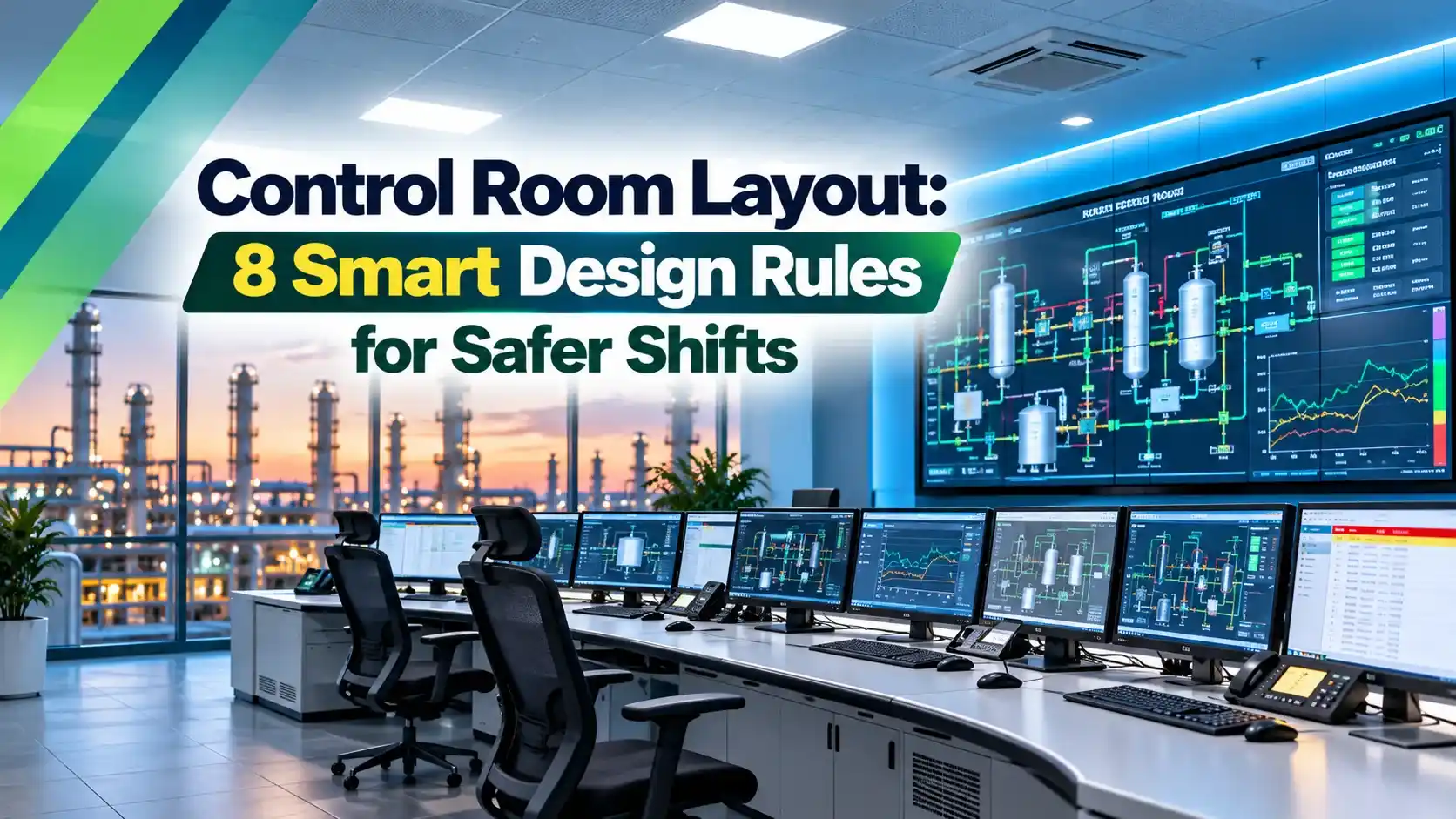
A control room is far more than a hall full of screens. This guide explains how ISO 11064, console arrangement, sightlines, rack rooms, siting, HVAC and lighting come together in a practical control room layout for process plants.
What Is Control Room Layout?
Control room layout is the planned arrangement of operator consoles, displays, support rooms and building services so that operators can monitor and control the process safely and comfortably. In a modern plant it is the home of the distributed control system operator stations, the safety system interfaces and the communication tools.
The layout covers several levels: the site location of the building, the grouping of rooms, the position of each console and finally the dimensions of each workstation. Mistakes at any level are expensive to correct once the plant is running.
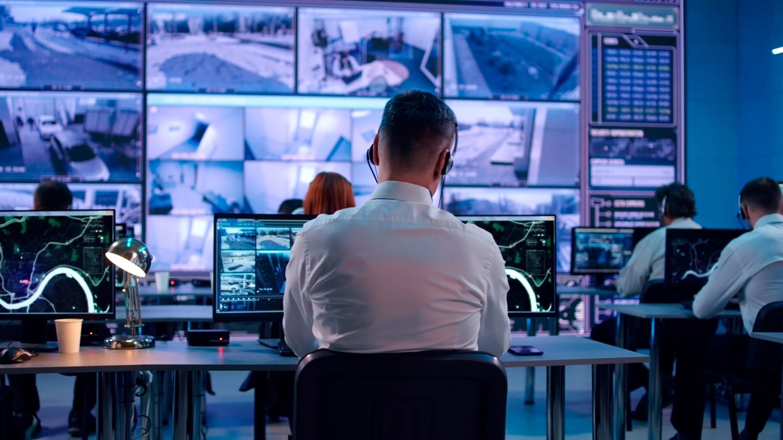
Mary Ann Lane and Peggy Hewitt of BAW Architecture write in Control Global that the size and quantity of consoles should dictate the size of the room. In other words, you design from the operator outward, not from the building inward.
ISO 11064 and the Seven Parts
ISO 11064 is the main international standard for the ergonomic design of control centres, and Control Global notes that its first parts were published in 2000. Motilde lists its seven parts as design principles, arrangement of control suites, control room layout, workstation layout and dimensions, displays and controls, environmental requirements and evaluation.
The UK Health and Safety Executive points to ISO 11064 as guidance for new control rooms and for upgrades where problems are known. It also refers to EEMUA 201 for practical guidance on process control desks and screens.
Control Global cites a 2002 Shell study by Harrie Rensink that estimated up to 15 percent capital savings when control rooms are designed correctly the first time. Rework after commissioning is far more costly.
Console Arrangement in a Control Room Layout
The console arrangement decides who can see whom, who can see the shared displays and how far people walk during an upset. Each operator position normally holds several HMI screens, a keyboard, a phone and radio, and sometimes a hardwired panel.
Consoles side by side facing one wall.
Consoles on a curve facing a shared video wall.
Small groups around a shared task or unit.
Shift supervisor placed behind and slightly above the operators.
Hardwired emergency push buttons and the emergency stop panel must be within easy reach of the responsible operator. Older plants also keep a mimic panel, but most new designs replace it with a large overview display.
Build a full size mock up of one console with cardboard or foam and let real operators sit at it. Reach, sightline and leg room problems show up in minutes.
Sightlines and Video Wall Readability
Every operator must be able to read the shared overview display from the normal seated position, without standing or leaning. Readability depends on the character height and the viewing distance, which together give the visual angle in arc minutes.
Extron, citing the videowall book by Robert Simpson, gives 10 arc minutes as the bare minimum for legible text and 15 to 20 arc minutes for the furthest viewer as a safer rule. A good control room layout checks this for the operator seated furthest from the wall.
D = viewing distance in mm, θ = visual angle in arc minutes
The angle ÷ 60 is in degrees
Example: D = 5 m = 5000 mm, θ = 20 arc minutes
θ ÷ 60 = 0.3333 degrees, tan(0.3333 degrees) = 0.005818
h = 5000 × 0.005818 = 29.1 mm
Control Room Layout Text Size Calculator
Second Worked Example for a Larger Room
In a larger central room, the furthest operator sits 8 m from the video wall. At 20 arc minutes the minimum character height is 8000 × 0.005818, which is about 46.5 mm.
If the overview graphics use smaller text, either move the consoles closer, enlarge the wall or redesign the overview with fewer, bigger values. Display design rules for this are covered in ISA 101 HMI screen design.
8 Smart Control Room Layout Design Rules
These rules follow the operator centred approach behind ISO 11064, which Motilde summarises as task analysis, user involvement and an interdisciplinary design team. Motilde also recommends a post occupancy evaluation after commissioning to collect operator feedback.
Rack Room, Marshalling and Support Rooms
System cabinets, servers and marshalling cabinets belong in a separate rack room or equipment room, not in the operator space. This keeps fan noise and heat away from operators and lets technicians work without disturbing the shift.
Field cables arrive through a cable cellar or raised floor and land on marshalling before reaching the I/O cards, as shown in field instrument to system cabinet wiring. Redundant DCS network cables should follow separate routes so one damaged tray cannot cut both.
| Room or Zone | Main Contents | Layout Note |
|---|---|---|
| Operator room | Consoles, video wall | Quiet, controlled lighting |
| Supervisor and shift office | Desk, meeting table | Visual contact with operators |
| Rack or equipment room | DCS, SIS, network, marshalling | Close by, separate air conditioning |
| Engineering room | Engineering stations | Away from operator traffic |
| UPS and battery room | UPS, batteries, distribution | Ventilated, fire separated |
| Welfare areas | Pantry, toilets, rest room | Near but outside the operator room |
Power for consoles and cabinets comes from a UPS with battery backup, and the clean instrument earth must be planned with the building earth as described in earthing aspects in process plants.
Siting and Blast Resistance
Control Global notes that after the 2005 BP Texas City explosion, the American Petroleum Institute issued API RP 752 for permanent occupied buildings and API RP 753 for portable buildings. These guide the risk based siting of control rooms and the decision to build them blast resistant.
In Indian oil and gas plants, OISD STD 118 sets layout and spacing rules, and OISD STD 163 deals specifically with process control rooms. Air intakes of a pressurised building are usually fitted with gas detection tied to the fire and gas system, so that toxic or flammable gas can shut the dampers.
Many modern refineries place the central control room well away from process units and keep only small field auxiliary rooms near the plant. Remote siting improves safety, but HSE research found it can cut face to face contact with field operators.
HVAC, Lighting and Acoustics
Motilde recommends room temperatures of 20 to 24 °C in winter and 23 to 26 °C in summer, and siting the room away from vibration sources such as generators and compressors. The HVAC system should be redundant, because computers and operators both suffer quickly without cooling in Indian summers.
Lighting should be indirect, dimmable and free of glare on screens, with no bright windows behind the displays. Use the methods in lighting design calculation for the lux level, and choose matt finishes, which Control Global gives as reflectance values of 0.2 to 0.3 for floors and 0.5 to 0.6 for walls.
Fit separate lighting zones over consoles, the video wall and circulation areas. Night shift operators can then dim the console zone while visitors walk through a lit corridor.
Alarm Displays and Operator Workload
The layout must support alarm handling, so the alarm summary screen should sit in the primary field of view of each operator. Good alarm management to ISA 18.2 and clear priorities reduce the load that no layout can fix on its own.
- Task analysis completed for normal, upset and emergency modes
- Console count and positions agreed with operations
- Video wall readable from the furthest seated position
- Rack room, UPS and battery room separated from operators
- Siting study done for blast, fire and toxic gas
- HVAC with redundancy and gas detection at intakes
- Glare free, dimmable lighting and acoustic treatment
- Operator review of mock up and final drawings
Benefits and Challenges of a Good Layout
- Faster, calmer response during upsets.
- Better teamwork and communication on shift.
- Less fatigue and fewer human errors.
- Lower rework cost after commissioning.
- Needs early input from operations and HSE.
- Blast resistant buildings cost more.
- Redundant HVAC and UPS add space and cost.
- Future expansion is hard to predict.
India Practice and Common Mistakes
In Indian brownfield plants, a common problem is adding new DCS consoles into an old room until sightlines and walkways disappear. During a FAT and SAT, check console positions and screen layouts together, not only the software.
Other mistakes include placing the video wall opposite windows, putting printers beside consoles and forgetting space for future units. A control room layout that reserves spare console positions and cable entries saves a shutdown later.
NUREG 0700 Human System Interface Guidelines
Control Room Design Basics Video
Control Room Layout FAQ
It is the planned arrangement of consoles, displays, support rooms and services in a control centre. It covers everything from building siting down to the dimensions of each workstation.
A good layout lets operators see shared displays, talk to each other and reach controls easily. It also keeps noisy equipment and visitors away from the consoles.
ISO 11064 is the main international standard for the ergonomic design of control centres. It has seven parts, from design principles to control room layout, workstations, displays, environment and evaluation.
The UK HSE refers to it as useful guidance for new rooms and for upgrades. EEMUA 201 adds practical advice on process control desks and screens.
An arc or horseshoe facing a shared video wall suits most central control rooms with several units. A simple linear row works well for small rooms with one or two operators.
Clusters suit large sites where teams handle separate areas. The final control room layout should come from task analysis and operator reviews, not from appearance.
It depends on the viewing distance and the visual angle you accept. Extron gives 15 to 20 arc minutes as a safe rule for the furthest viewer.
At 5 m and 20 arc minutes, characters should be about 29 mm tall. At 8 m the same angle needs about 46.5 mm, so plan the wall and graphics together.
System cabinets and servers produce heat and fan noise that tire operators over a long shift. Technicians also need easy access without walking through the busy operator space.
A separate rack room can have its own dedicated cooling, fire protection and access control. It still sits close enough to keep cable routes short and practical.
It depends on the siting study for the plant and the possible explosion overpressure. API RP 752 guides the risk based siting of permanent occupied buildings.
In Indian oil and gas plants, OISD STD 118 and OISD STD 163 also apply. Many sites now choose remote siting plus a pressurised, blast resistant building for the central control room.
Motilde recommends 20 to 24 °C in winter and 23 to 26 °C in summer. Control Global reports an ambient noise range of 30 to 45 dB in ISO 11064.
Lighting should be indirect, dimmable and free of glare on the screens. Redundant HVAC and UPS supplies keep both people and computers working during failures.
Related Articles
- Distributed Control System DCS
- SCADA HMI Screen Design ISA 101
- Alarm Management ISA 18.2
- Marshalling Cabinet DCS Wiring
- Fire and Gas System in Process Plants
External References
- NUREG 0700 Rev 3, Human System Interface Design Review Guidelines, US NRC
- What Does Good Control Room Design Look Like, Control Global
- Control Room, Wikipedia
What We Learn Today
- A control room layout is planned from the operator outward, so the number and size of consoles set the room size, as Control Global advises.
- ISO 11064 has seven parts covering principles, suites, room layout, workstations, displays, environment and evaluation for every control centre project.
- Check video wall text with the visual angle formula, separate the rack room, and site the building for blast, fire and toxic gas risks.
