
LOPA is a semi-quantitative method to determine whether existing safeguards are sufficient and, if not, what SIL a new Safety Instrumented Function (SIF) must achieve to reduce risk to a tolerable level.
This guide explains the LOPA method step by step, defines Independent Protection Layers (IPLs), shows a worked reactor overpressure example, and includes a live LOPA SIL calculator.
LOPA sits between a qualitative hazard study (HAZOP) and a full quantitative risk assessment. It is more rigorous than a HAZOP because it puts numbers on frequencies and probabilities.
It is faster than a full QRA because it uses order-of-magnitude approximations rather than site-specific modelling. Most SIL determinations in the process industry are made using LOPA.
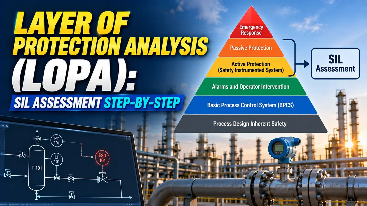
What Is LOPA and When Is It Used?
A LOPA scenario represents one specific accident sequence: one initiating event (a cause) leading to one consequence (a harm) through a defined set of safeguards. Each LOPA scenario is analysed independently.
The output of a LOPA scenario is a mitigated consequence frequency — the estimated frequency at which the consequence reaches people or equipment at risk, after all existing safeguards have been credited.
This mitigated frequency is compared against a tolerable risk target. If it exceeds the target, additional risk reduction is required — typically a SIF at a specific SIL.
Before LOPA became standardised, SIL determination was often done qualitatively using risk matrices — a process that was faster but had no traceable numeric basis. LOPA gave the industry a defensible, documented method that sits between the speed of qualitative risk matrices and the rigour of full quantitative risk assessments.
IEC 61511-3 (the process sector application standard for functional safety) now includes LOPA as one of the recommended methods for SIL determination in its Annex F, alongside risk graphs and risk matrices.
LOPA Method: 7 Steps for SIL Determination
Identify one initiating event (a cause) and one undesired consequence. The consequence category determines the tolerable risk target — companies use different targets for different severities (toxic release, fire, explosion, environmental damage).
A LOPA scenario is always one-to-one: one initiating event, one consequence. If a single initiating event can cause two different consequences, two separate LOPA scenarios are required.
The IEF is the frequency at which the initiating event occurs, before any safeguards act. LOPA uses generic industry data rather than site-specific failure data.
Typical values: control loop failure 0.1 to 1 per year, operator error 0.1 per demand, PRV failure to open 0.01 per demand.
The IEF is the starting frequency in the LOPA calculation. All IPL credits are applied as multipliers to this frequency.
An IPL is a device, system, or action that prevents the consequence independently of the initiating event and all other IPLs. Each IPL is assigned a Probability of Failure on Demand (PFD).
To qualify as an IPL, a safeguard must be independent of the initiating event and other IPLs, capable of preventing the consequence on its own, auditable, and dependable.
A BPCS loop can be credited as one IPL only if it is independent of the initiating event. A SIS is always treated as a separate IPL from the BPCS.
Some scenarios only reach a consequence under specific conditions — ignition requires an ignition source.
These are conditional modifiers: probabilities multiplied into the scenario for the fraction of demands that lead to the consequence.
Common conditional modifiers: probability of ignition (0.01 to 0.5), probability of personnel in the hazard zone, probability of fatal injury given exposure. They reduce the scenario frequency before or after IPL credits.
Multiply the IEF by the PFD of each IPL and all conditional modifiers. The product is the mitigated consequence frequency — how often the consequence reaches people or assets at risk.
Formula: Mitigated frequency = IEF × PFD(IPL1) × PFD(IPL2) × ... × conditional modifiers
Compare the mitigated consequence frequency against the tolerable risk target. Typical targets for a fatality consequence: 1×10⁻⁴ per year to 1×10⁻⁵ per year. Some companies use 1×10⁻⁶ per year for catastrophic scenarios.
If the mitigated frequency is below the target, no additional risk reduction is required. If it exceeds the target, the gap must be closed by a new SIF at a defined SIL.
If a new SIF is required, divide the tolerable risk target by the mitigated frequency without the SIF.
The PFD result maps to a SIL per IEC 61511: PFD 0.1 to 0.01 is SIL 1, PFD 0.01 to 0.001 is SIL 2, PFD 0.001 to 0.0001 is SIL 3.
This SIL becomes the design target for the SIS. See the SIL verification vs validation guide for how the SIL is confirmed after design.
The most common LOPA credit error is counting a control loop as an IPL in a scenario where that same loop's failure is the initiating event. If the high-pressure control loop failure is the cause of the scenario, the same loop cannot also be credited as a protection layer against its own failure.
A separate independent high-pressure alarm with operator response is a valid IPL (PFD typically 0.1) if the alarm and the control loop use different sensors. A pressure relief valve is a valid IPL (PFD typically 0.01) if it is sized and set correctly for the scenario. Always check independence before crediting any safeguard.
IPL PFD Reference Values Used in LOPA
| Protection Layer | Typical PFD Credit | IPL Qualification Notes |
|---|---|---|
| BPCS control loop (independent of IE) | 0.1 | Only one BPCS credit per scenario. Sensor must be independent of the IE sensor. |
| High alarm with operator response (independent sensor) | 0.1 | Operator must have adequate time to respond. Response procedure must be documented and trained. |
| Pressure Relief Valve (PRV) to safe location | 0.01 | PRV must be correctly sized for the scenario. Inlet and outlet line design must be per API 520/521. |
| Rupture disc (upstream of PRV) | 0.01 | Can be combined with PRV as a single IPL — the combination PFD is the product of both. |
| Safety Instrumented Function (SIS) — SIL 1 | 0.01 to 0.1 | PFD must be confirmed by SIL verification per IEC 61511-1. |
| Safety Instrumented Function (SIS) — SIL 2 | 0.001 to 0.01 | PFD must be confirmed by SIL verification. Redundancy typically required. |
| Safety Instrumented Function (SIS) — SIL 3 | 0.0001 to 0.001 | High redundancy and diagnostic coverage required. Rarely achieved with a single sensor/actuator pair. |
| Dike or bund (for liquid containment) | 0.01 | Valid IPL only when consequence is spill to environment or fire, not vapour cloud explosion. |
| Emergency isolation valve (manual) | 0.1 | Only if operator has adequate response time and the valve is accessible during the scenario. |
| Operator response to BPCS alarm (non-SIS) | 0.1 | One operator response credit per scenario. Multiple alarm credits cannot both be taken if the same operator responds. |
Running the LOPA Numbers on a Reactor Overpressure Scenario
Suppose a batch reactor has a runaway reaction scenario. The initiating event is loss of cooling water, estimated at 0.1 per year from generic data.
The consequence is reactor overpressure leading to rupture and toxic release causing potential fatality. The company tolerable risk target for a fatality scenario is 1×10⁻⁴ per year.
IEF: 0.1 per year (generic data for utility supply failure)
Consequence: Reactor overpressure, rupture, toxic release, fatality
Existing IPLs:
IPL 1: High temperature alarm (independent sensor) with operator response
PFD = 0.1 (one BPCS alarm credit, operator has 15 min to respond)
IPL 2: Pressure relief valve set at 110% MAWP, discharging to safe vent
PFD = 0.01 (PRV correctly sized for runaway scenario per API 520)
Conditional modifier: Probability of personnel in hazard zone = 0.25
(plant personnel present in the area 6 hours per 24-hour shift)
Mitigated frequency (without SIF):
= IEF × PFD(IPL1) × PFD(IPL2) × P(personnel in zone)
= 0.1 × 0.1 × 0.01 × 0.25
= 2.5×10⁻⁵ per year
Compare to tolerable risk target: 1×10⁻⁴ per year
2.5×10⁻⁵ is below 1×10⁻⁴ — risk is TOLERABLE without a SIF
Now suppose the PRV is not available (being tested). Removing IPL 2:
= 0.1 × 0.1 × 0.25 = 2.5×10⁻³ per year — EXCEEDS target by 25×
Required SIF PFD = Target / (IEF × IPL1 × conditional) = 1×10⁻⁴ / 2.5×10⁻³ = 0.04
PFD 0.04 falls within SIL 1 range (0.01 to 0.1) → SIF required at SIL 1
This is intentional. LOPA's founders recognised that the uncertainty in generic failure data is typically a factor of 3 to 10. Using precise-looking values like 0.087 per year instead of 0.1 per year creates a false impression of accuracy that is not supported by the data quality.
OOM values also make arithmetic fast and auditable. A reviewer can check the frequency multiplication in seconds. If a scenario requires more precision — for example, when the LOPA result is right on the boundary between two SILs — the company should escalate to a full fault tree analysis rather than trying to tune the LOPA input data.
LOPA SIL Calculator
Watch: Layer of Protection Analysis — The Bridge from HAZOP to SIL (2025)
LOPA Questions Process Safety Engineers Ask
Related Articles on This Site
- What Is SIL? Safety Integrity Level Explained
- SIL Verification vs SIL Validation: What Is the Difference?
- Safety Instrumented Function (SIF) Design Explained
- Safe Failure Fraction Explained in Functional Safety
- Process Safety vs Functional Safety: Key Differences
External References
- ISA-84 / IEC 61511: Functional Safety — Safety Instrumented Systems for the Process Industry | ISA
- CCPS Layer of Protection Analysis: Simplified Process Risk Assessment | AIChE CCPS (2001)
What We Learn Today
- LOPA is a 7-step semi-quantitative method: define the scenario, assign the initiating event frequency, identify IPLs and their PFDs, apply conditional modifiers, calculate the mitigated consequence frequency, compare against the tolerable risk target, and determine the required SIF SIL. The key formula is: Mitigated frequency = IEF × PFD(IPL1) × PFD(IPL2) × conditional modifiers.
- An IPL must be independent of the initiating event and all other IPLs, capable of preventing the consequence on its own, auditable, and dependable. A BPCS control loop can only be credited once per scenario, and never in a scenario where that loop's own failure is the initiating event.
- SIL is determined from LOPA by dividing the tolerable risk target by the mitigated consequence frequency without the SIF. The ratio gives the required SIF PFD, which maps to SIL 1, 2, or 3 per IEC 61511. LOPA is a design input — SIL verification confirms whether the actual SIS design achieves that PFD target.