
A burner that lights on too little gas can lift its flame, and one that fires on too much can overheat or puff back. Small diaphragm switches on the gas train watch both limits and the combustion air, and stop the burner before trouble starts.
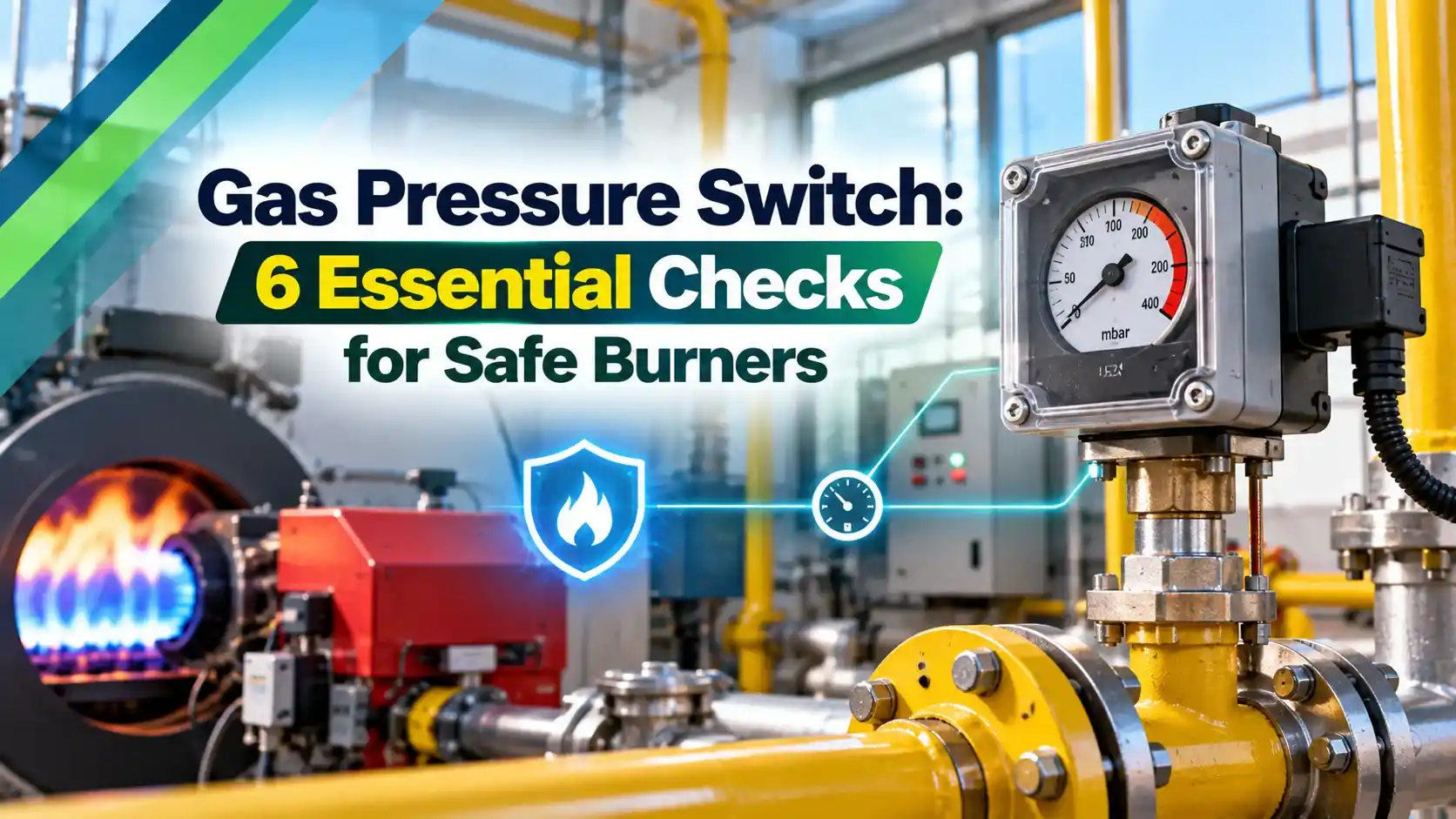
Every boiler, furnace and thermic fluid heater fired on natural gas or LPG relies on pressure switches as safety interlocks. A correctly set and tested gas pressure switch stops the burner before low or high fuel pressure turns into an unsafe flame.
What Is a Gas Pressure Switch?
A gas pressure switch is a safety device that opens or closes an electrical contact when fuel gas or combustion air pressure crosses a set value. On industrial burners it acts as an interlock in the burner management system, which will not start or keep running the burner unless every switch reports a safe condition.
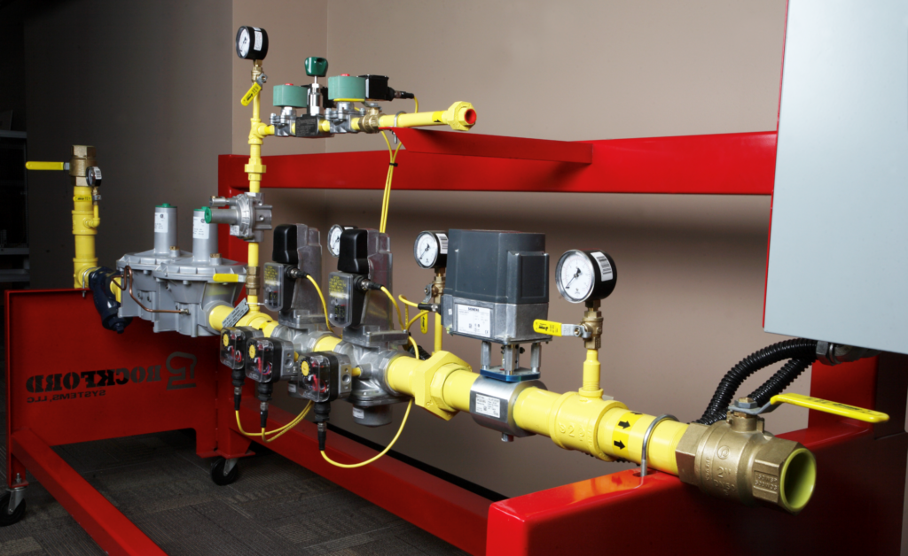
Rockford Systems explains that a typical valve train carries both a low gas switch and a high gas switch. At each call for heat, the burner management system checks both before it starts the purge cycle.
The device is a close cousin of the general purpose pressure switch, but it is built and approved for flammable gases and very low pressures, often just a few millibar. That is why it uses a large, soft diaphragm instead of a Bourdon tube or piston.
Inside a Diaphragm Gas Pressure Switch
Gas pressure acts on one side of a rubber diaphragm, while an adjustable spring pushes from the other side. When the gas force beats the spring force, the diaphragm moves and snaps a microswitch over.
Turning the hand wheel changes the spring preload and so the switching point. The Honeywell Kromschroeder DG range covers about 0.4 to 500 mbar across its models, with an NBR diaphragm as standard.
Most units have a changeover contact. The Elster operating instructions state that contacts 3 and 2 close on rising pressure and contacts 1 and 3 close on falling pressure, so one model can serve as either a low or a high switch, a choice explained in pressure switch vs pressure transmitter.
A difference of only a few millibar matters on a gas burner. 10 mbar is roughly 100 mm of water column, about the height of a coffee cup.
Three Duties of a Gas Pressure Switch on a Burner
Trips when gas pressure falls below the level at which the burner can fire properly.
Trips when pressure rises too far, usually after a regulator failure.
Proves that the combustion air fan is running and delivering pressure before purge and ignition.
The National Board of Boiler and Pressure Vessel Inspectors describes the low gas switch as sensing pressure in the range where the burner cannot properly operate. Both low and high switches should lock out and need a manual reset, which forces the operator to look for the cause.
High gas pressure is most often caused by a failed regulator. The air switch is a differential type in many burners, connected to both sides of the fan, so it proves real air flow rather than just a static pressure.
A fourth use is valve proving, where a gas pressure switch between two safety shut off valves checks that the space between them holds or loses pressure as expected. This leak test is closely related to leak testing practice in the field.
Where Each Switch Sits in the Gas Train
Heating Help notes that the low gas switch comes after the gas pressure regulator, while the high gas switch sits between the last manual gas valve and the burner. The safety shut off valves are usually solenoid valves that close on loss of power.
The same guide adds that these switches are typically fitted when the burner rating exceeds 2,500,000 Btu per hour.
Fit a small test cock or test nipple next to every gas pressure switch. It lets you connect a gauge and bleed or apply pressure without breaking the main pipework.
Standards and Approvals
In Europe, switches for gas and air are tested to EN 1854, and Honeywell lists CE marking under the Gas Appliances Regulation (EU) 2016/426. The same DG family is certified for SIL 3 to EN 61508 and PL e to ISO 13849.
The Elster instructions add that one switch suits SIL 2 or PL d, while two redundant switches are needed for SIL 3 or PL e at system level. This fits the wider SIF design rule that the whole loop, not one device, sets the achieved integrity.
Trip and Reset Point Formula
Every switch has a switching differential, the band between where it trips and where it resets. This works like the deadband described in deadband in pressure switches, and it decides how far pressure must recover before the burner can restart.
High gas switch: trips at S high on rising pressure, resets at S high minus differential
Margin below normal = (P normal minus S low) ÷ P normal × 100
Example:
P normal = 20 mbar, S low = 15 mbar, S high = 30 mbar, differential = 0.9 mbar
Low resets at 15 + 0.9 = 15.9 mbar, high resets at 30 minus 0.9 = 29.1 mbar
Margins = 25.0 % below and 50.0 % above normal
Some dials show the rising and others the falling switching point, so read the datasheet first. The calculator below assumes you set the trip value directly.
Gas Pressure Switch Setpoint Calculator
Second Worked Example: Allowing for Dial Tolerance
The Elster data gives an adjusting tolerance of ±15 percent of the scale value. If the dial of a DG 30 is set at 15 mbar, the real switching point may lie anywhere from 15 × 0.85 = 12.75 mbar to 15 × 1.15 = 17.25 mbar.
That is why the dial is only a starting point and every gas pressure switch must be set against a test gauge. For imperial gauges, remember that 1 mbar is about 0.40 inch of water column, so 15 mbar reads close to 6 inch WC.
Setting a Gas Pressure Switch Step by Step
This follows the procedure in the Elster operating instructions. A hand pump with a fine vernier, or a multifunction process calibrator with a low pressure module, makes the slow ramp much easier.
Mount the switch with the diaphragm vertical whenever possible. Elster warns that other positions shift the switching point, so recheck the setting if the unit has to be mounted differently.
Choosing the Right Gas Pressure Switch Range
| Model | Adjusting Range, mbar | Switching Differential, mbar | Typical Use |
|---|---|---|---|
| DG 6 | 0.4 to 6 | 0.2 to 0.3 | Air proving, low draft |
| DG 10 | 1 to 10 | 0.25 to 0.4 | Combustion air |
| DG 30 | 2.5 to 30 | 0.35 to 0.9 | Low pressure natural gas |
| DG 50 | 2.5 to 50 | 0.8 to 1.5 | Gas after the regulator |
| DG 150 | 30 to 150 | 3 to 5 | Medium pressure gas |
| DG 500 | 100 to 500 | 8 to 17 | Upstream of regulators |
Choose a range so the setpoint falls in the middle third of the scale, where the dial is easiest to read and adjust. Check the gas group and area classification as well, using gas groups IIA, IIB and IIC, because Ex zones need suitably certified switches or isolating amplifiers.
6 Essential Gas Pressure Switch Checks
- Trip point verified against a test gauge, rising and falling.
- Manual reset works and the burner cannot restart without it.
- Tightness of all pressure ports confirmed with a leak test.
- Wiring fails safe, so a broken wire stops the burner.
- Vent or breather port clean and protected from water.
- Settings, test results and seals recorded in the log.
Honeywell recommends checking these switches at least once a year, or twice a year for biogas. The Elster instructions repeat the tightness test after any maintenance work on the train.
Applications Beyond Boilers
In a plant DCS or PLC, each switch trip should appear as a separate alarm so the operator sees which interlock acted first. A first out alarm scheme is the standard way to capture that order.
Troubleshooting Nuisance Trips
Low gas trips during light up often come from a slow regulator or an undersized supply line that dips when the valves open. Log the pressure at the switch test point during start up, and compare it with the setpoint tips in pressure switch setpoint and deadband.
Air switch trips usually point to blocked inlet filters, a slipping fan belt, water in the sensing tubes or a cracked hose. Check the tube routing first, because condensate in a low point can hold the diaphragm in the wrong position.
The National Board notes that a burner prepurge provides at least four air changes of the combustion chamber and gas passes. The air proving switch is what confirms the fan really delivered that air.
- Simple, robust and needs no power to sense pressure.
- Very sensitive at a few millibar.
- Approved designs available up to SIL 3 with redundancy.
- Easy to test with a gauge and ohmmeter.
- Dial setting has a wide tolerance.
- No live reading of the actual pressure.
- Diaphragm ages and needs periodic replacement.
- Mounting position affects the switching point.
Elster DG Pressure Switch Operating Instructions
Pressure Switch Overview Video
Gas Pressure Switch FAQ
It opens or closes a contact when gas or air pressure crosses a set value. The burner management system uses that contact as a safety interlock before and during firing.
If the pressure goes out of limits, the burner is shut down or prevented from starting. Low gas, high gas and air proving duties all use the same basic design.
It is fitted downstream of the gas pressure regulator and before the two safety shut off valves. That position proves the regulated pressure that the burner will actually receive.
A test point beside it lets a technician connect a gauge for routine checks. The switch should lock out and need a manual reset after every trip.
The most common cause is a regulator that has failed open or is creeping under no flow. A blocked regulator vent line or a wrong spring can have the same effect.
Never just reset and restart after a high gas trip. Check the regulator, lock up pressure and settings before the burner is allowed to fire again.
It is a pressure or differential switch that proves the combustion air fan is running. It must make before purge timing starts and must stay made during firing.
Many burners connect it across the fan inlet and outlet to sense real air flow. A blocked tube or a slipping belt is a common cause of a trip.
Elster gives an adjusting tolerance of ±15 percent of the scale value for its DG switches. A dial set at 15 mbar may therefore trip anywhere between 12.75 and 17.25 mbar.
This is why the dial is only a starting point for the setting. Always confirm the real trip value with a test gauge and record it.
In Europe, gas and air pressure switches are tested to EN 1854 and carry CE marking under the Gas Appliances Regulation. Many approved switches are also certified to EN 61508 and ISO 13849.
In the USA, ASME CSD 1 and NFPA codes cover fuel pressure supervision. Indian plants usually follow the burner maker and insurer requirements.
Honeywell recommends a function and tightness check at least once a year. Plants burning biogas should check twice a year because of the harsher gas.
Many plants also test every trip point during the annual boiler shutdown. Record the trip value, the reset value and the condition of the seal each time in the log.
Related Articles
- What Is a Burner Management System
- What Is a Pressure Switch
- Deadband in Pressure Switches
- Solenoid Valve Working Principle
- First Out Alarm PLC Logic
External References
- Pressure Switches for Gas DG..B and DG..U Operating Instructions, Elster
- Kromschroeder DG Pressure Switches for Gas, Honeywell
- Pressure Switch, Wikipedia
What We Learn Today
- A gas pressure switch uses a diaphragm against an adjustable spring to trip a contact at a set pressure, often only a few millibar.
- Low gas switches sit after the regulator, high gas switches sit near the burner, and air proving switches confirm the fan before purge.
- Dial tolerance can be ±15 percent, so a 15 mbar setting may trip between 12.75 and 17.25 mbar unless checked with a gauge.
