
The electronics of a non contact radar level transmitter set its accuracy, but the antenna decides where the energy goes and how much returns. Picking the right shape, size and frequency often turns a troublesome tank into an easy one.
Horn, rod, parabolic, lens and drop antennas each focus microwaves differently. This guide explains every radar antenna type, beam angle rules, nozzle limits and how to beat condensation and buildup.

What Is a Radar Antenna in Level Measurement?
A radar antenna is the part of a non contact level transmitter that launches microwaves toward the product and collects the echo that comes back. The electronics measure the time or frequency difference, and the radar level transmitter turns it into distance and level.
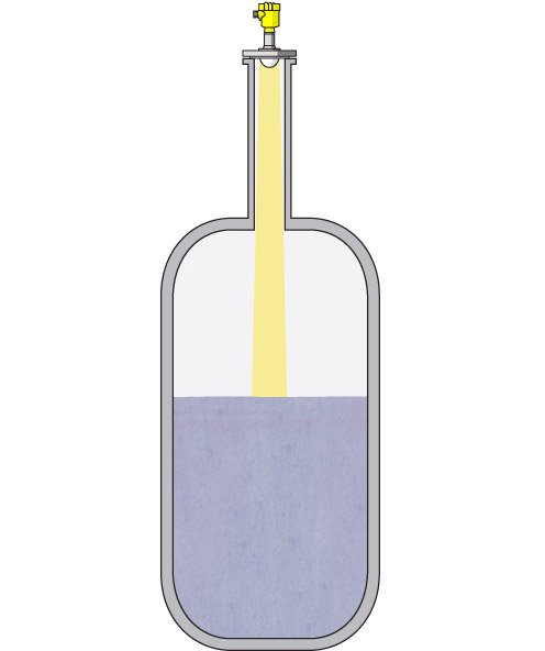
The antenna shape and diameter set the beam angle, the gain and the near zone where readings are unreliable. A focused beam puts more energy on the surface and less on walls, ladders and agitators, which reduces the false echoes discussed in radar false echo handling.
Guided wave radar uses a probe instead of a free space beam, so it does not need any of the antennas described here. The choice between the two families is compared in guided wave radar vs non contact radar.
Frequency, Radar Antenna Size and Beam Angle
The beam angle of a radar antenna depends on the ratio of wavelength to antenna diameter. Higher frequency means a shorter wavelength, so the same antenna gives a narrower beam, or a smaller antenna gives the same beam.
VEGA reports that its 80 GHz VEGAPULS 64 reaches a beam angle of about 3 degrees with an antenna of about 80 mm, compared with about 10 degrees for a traditional 26 GHz sensor. Control Global adds that the narrower beam is about one fourth as wide as a 10 degree beam.
Control Global also notes a jump in dynamic range from 96 dB for a 26 GHz sensor to 120 dB at 80 GHz. KROHNE states that at 10 m the beam of its 80 GHz radar is only 30 % as wide as that of a 24 GHz device.
At 80 GHz the wavelength in air is only about 3.75 mm, compared with about 11.5 mm at 26 GHz. That threefold shorter wavelength is the whole reason the radar antenna can be so much smaller for the same focus.
Beam Angle and Footprint Formula
A useful rule of thumb gives the half power beam angle of a circular aperture from the wavelength and antenna diameter. Real antennas differ slightly, so always confirm with the data sheet value.
Beam angle θ (degrees) ≈ 70 × λ ÷ D
Footprint width W = 2 × L × tan(θ ÷ 2)
Example: f = 80 GHz, D = 80 mm, L = 10 m
λ = 299.79 ÷ 80 = 3.747 mm
θ = 70 × 3.747 ÷ 80 = 3.28°
W = 2 × 10 × tan(1.64°) = 0.57 m
The same 80 mm horn at 26 GHz gives about 10.09 degrees and a footprint of about 1.77 m at 10 m. That wider spot is far more likely to touch a wall, a ladder or a heating coil.
Radar Antenna Beam Calculator
6 Essential Radar Antenna Types
Metal cone flares out from a waveguide to focus the beam.
PTFE or PP rod radiates from its full length.
A dish reflects energy into a very narrow beam.
A PEEK or PTFE lens focuses the beam, often flush.
Encapsulated PTFE or PP cover protects the horn.
Flat array of radiating elements, used in custody tank gauging.
The horn is the workhorse radar antenna, and Emerson lists cone sizes with beam angles of 22 degrees at 1.5 inch, 18 at 2 inch, 14 at 3 inch and 10 at 4 inch for its 26 GHz Rosemount 5408. Bigger horns give narrower beams but need bigger nozzles.
A rod radar antenna sacrifices focus for corrosion resistance and fit small threaded connections, which helps in level measurement in corrosive chemicals. Its wide beam makes it a poor choice in tall, cluttered vessels.
The parabolic radar antenna gives the narrowest 26 GHz beam, which Emerson states as 4.5 degrees for an 8 inch dish, and suits dusty solids such as those in slurry and solids service. Many dish versions add air purge connections to clear dust.
Before ordering, compare the antenna diameter with the actual nozzle bore, not the nominal size. A 4 inch horn will not pass through a schedule 160 nozzle with a reduced inside diameter.
Lens and Encapsulated Designs at 80 GHz
KROHNE explains that 80 GHz focusing is so effective that a flush mounted PEEK lens antenna is enough for most duties, without a large horn. A flush lens leaves no cavity for product or condensate to collect.
Drop and process seal versions cover the metal parts with PTFE or PP, so condensate runs off instead of hanging in the horn. Control Global mentions such drop antennas for condensing atmospheres, and they also help in high viscosity liquids that splash and coat.
A narrow 80 GHz beam can measure through a ball valve in some designs, letting the transmitter be isolated from the tank for service. Control Global lists this as one of the practical gains of the higher frequency.
Nozzle and Mounting Rules for Each Radar Antenna
Emerson states that its cone antenna should extend at least 0.4 inch below the nozzle and may be recessed up to 4 ft in smooth nozzles. VEGA notes that a focused 80 GHz beam reduces the effect of long mounting sockets that once caused strong interference.
Nozzle length matters because the inner wall reflects energy back as a ring down echo near the top of the range. Agitated tanks add another layer of difficulty, discussed in level measurement in agitated vessels.
| Situation | Preferred Antenna | Reason |
|---|---|---|
| Clean liquid, 2 inch nozzle | 80 GHz lens | Narrow beam from a small opening |
| Corrosive acid tank | Rod or PTFE drop | All PTFE wetted parts |
| Tall cement silo | Parabolic with purge | Narrow 26 GHz beam, dust cleaning |
| Hygienic food vessel | Flush lens or process seal | No cavities, CIP friendly |
| Still pipe in tank farm | Horn or planar array | Matched to pipe diameter |
| Condensing reactor | Drop or flush lens | Condensate runs off |
Condensation, Buildup and Still Pipes
Water droplets inside a horn absorb and scatter microwaves, so the echo weakens or a fixed false echo appears near the antenna. Insulating the nozzle, using a flush lens and choosing an encapsulated radar antenna all help, and foam problems are covered in why foam affects level sensors.
A still pipe, also called a stilling well, guides the microwaves and calms a turbulent surface. The horn diameter must match the pipe, the pipe must be smooth inside, and slots should be on one side only, as with bypass level chambers.
Still pipes are standard in custody transfer, where an automatic tank gauging system needs millimetre accuracy. Planar array and large horn antennas are common in these installations.
On solids silos, aim the antenna toward the outlet cone so the beam meets the sloping surface more squarely. Many manufacturers supply swivel flanges for exactly this adjustment.
- Strong echo even on weak reflectors
- Fewer false echoes from internals
- Fits the existing nozzle without changes
- Tolerates condensate and buildup
- Longer range and better accuracy
- Larger horns and dishes need large nozzles
- Rod antennas have wide beams
- Plastic lenses have temperature limits
- Purge air adds utility cost
- Still pipes need careful fabrication
Radar Antenna Selection Checklist
- Process temperature and pressure within antenna material limits
- Chemical compatibility of PTFE, PP, PEEK or stainless steel
- Nozzle bore, height and position checked against the data sheet
- Beam footprint at maximum distance clears walls and internals
- Condensation, coating or dust risk identified
- Frequency chosen, 26 GHz or 80 GHz
- Still pipe diameter and finish confirmed if used
- Hazardous area certification matched to the zone
Hazardous area marking applies to the whole transmitter, not just the electronics, so check the zone rules in hazardous area classification. For an overview of all level technologies, see how to select the right level sensor and types of level transmitters.
After commissioning, verify the reading at several levels, following the approach in level transmitter 5 point calibration. A product with a very low reflection may still need a larger antenna or a still pipe even at 80 GHz.
Rosemount 5408 Antenna Data Sheet
Radar Beam Angles Explained Video
Radar Antenna FAQ
It sends microwaves toward the product and collects the echo that returns. The shape and size of the radar antenna decide the beam angle and the signal strength.
A well focused antenna puts energy on the surface and avoids walls and internals. That gives a stronger echo and far fewer false readings over the full measuring range.
The wavelength at 80 GHz is about one third of that at 26 GHz. Beam angle is roughly proportional to wavelength divided by antenna diameter.
So the same size radar antenna gives a beam about three times narrower. VEGA reports a beam of about 3 degrees at 80 GHz against about 10 degrees at 26 GHz.
Use a rod radar antenna for aggressive chemicals and for small threaded process connections. Its PTFE or PP body resists most acids, alkalis and solvents very well.
The beam is wide, so it suits short ranges and small tanks without many internals. For tall or cluttered vessels, a lens or horn usually performs much better.
Yes, it gives the narrowest beam of the 26 GHz radar antenna family and works well in tall silos. Emerson lists 4.5 degrees for its 8 inch dish.
Many versions include an air purge connection to remove dust from the reflector. The large diameter, however, needs a big nozzle or a manway on the vessel roof.
The horn should usually extend slightly below the lower end of the nozzle. Emerson asks for at least 0.4 inch below the nozzle for its cone antenna.
Some designs allow recess in smooth nozzles up to a stated length. Always follow the radar antenna data sheet, since rough or long nozzles create strong near zone echoes.
Insulate or heat trace the nozzle and choose a flush lens or an encapsulated drop radar antenna. These shapes let droplets run off instead of collecting.
Run a fresh false echo map after cleaning or changing the radar antenna. Check the echo curve again during the cold season, when condensation is usually at its worst.
A still pipe helps with turbulent surfaces, foam and very low reflection products. It is also normal practice for custody transfer tank gauging in large tank farms.
The pipe must be smooth inside and match the radar antenna diameter closely. Slots should be in one straight line, and any welds inside should be ground flush.
Related Articles
- Radar Type Level Transmitter
- Radar Level Transmitter False Echo Handling
- Guided Wave Radar vs Non Contact Radar
- Radar Sensor VEGAPULS 42
- Automatic Tank Gauging Explained
External References
- Rosemount 5408 Non Contacting Radar Product Data Sheet, Emerson
- Reliable Level Measurement With Radar Under Difficult Conditions, VEGA
- Horn Antenna, Wikipedia
What We Learn Today
- A radar antenna sets the beam angle, roughly 70 times wavelength divided by diameter, so an 80 mm antenna at 80 GHz gives about 3 degrees.
- Horn, rod, parabolic, lens, drop and planar array antennas each suit different tanks, from corrosive acid service to tall dusty silos and custody tank farms.
- Nozzle length, condensation and still pipe quality matter as much as antenna type, so follow the data sheet and record a false echo map.