
Safety · Hazardous Area · ATEX · IECEx · Zone 0 · Zone 1 · Zone 2 · Ex Equipment
Hazardous Area Classification: Zone 0, Zone 1 and Zone 2 Explained with Gas Groups, Temperature Classes, Protection Methods and Equipment Marking
Hazardous area classification defines where flammable gases or vapours may be present in a process plant, and what protection standard electrical equipment must meet in each zone. Getting this wrong creates explosion risk. This guide covers Zone 0/1/2 definitions, IEC/ATEX and NEC/Division systems, gas groups, temperature classes, protection methods and how to read Ex equipment marking codes.
What Is Hazardous Area Classification and Why Does It Matter?
In oil and gas, petrochemical, chemical, pharmaceutical and many other process industries, flammable gases, vapours, mists or dusts can be present in the atmosphere under normal or abnormal operating conditions. If an ignition source (an electrical spark, a hot surface, static discharge) is present in the same location at the same time as an explosive atmosphere, the result is a fire or explosion.
Hazardous area classification is the systematic process of identifying which locations in a plant may contain an explosive atmosphere, classifying them into zones based on how frequently and for how long the hazardous atmosphere is likely to be present, and then specifying what protection standard all electrical and instrumentation equipment must meet for each zone. The classification determines what type of transmitter, junction box, motor, control panel, lighting or instrument cable you can install in each area.
Every instrument installed in a hazardous area including 4-20 mA transmitters, pressure switches, control valve positioners and temperature sensors: must carry the correct Ex certification for the zone it is installed in. Using uncertified equipment in a hazardous area is a regulatory violation and a serious safety risk.
Zone 0, Zone 1 and Zone 2: IEC 60079-10-1 Definitions
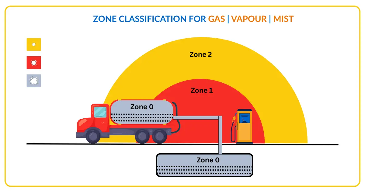
The international standard IEC 60079-10-1 (Explosive atmospheres: Classification of areas) defines three zones for gas and vapour hazards. The zone number reflects the frequency and duration of the explosive atmosphere. Zone 0 is the most hazardous (continuous presence); Zone 2 is the least hazardous (only in abnormal conditions).
Explosive atmosphere is present continuously or for long periods (more than 1,000 hours per year). Examples: inside storage tanks, inside pipes and vessels containing flammable liquids. Equipment must meet the highest protection standard: Category 1G (ATEX) or Ex ia intrinsic safety.
Explosive atmosphere is likely to occur under normal operating conditions (10 to 1,000 hours per year). Examples: around pump seals, flanges on hydrocarbon lines, open-ended sample connections, loading areas. Equipment must meet Category 2G (ATEX). Flameproof (Ex d), increased safety (Ex e) and intrinsic safety (Ex ia/ib) are all acceptable.
Explosive atmosphere is not likely under normal conditions, only in abnormal situations (less than 10 hours per year). Examples: general open areas of an oil and gas plant, outside flanged connections. Category 3G (ATEX). Non-sparking (Ex n), increased safety (Ex e) and pressurisation (Ex p) are commonly used.
Figure 1: Concentric hazardous zones around a typical ignition source in a process plant. Zone 0 is the innermost (continuous hazard, highest protection required). Zone 2 is the outermost (infrequent hazard, lower protection required). The zone boundaries are determined by gas dispersion modelling and process knowledge, not by fixed radii.
Zone 20, Zone 21 and Zone 22: Dust and Powder Hazards
Combustible dusts (grain, flour, coal, wood dust, metal powders) also form explosive atmospheres. IEC 60079-10-2 defines a parallel zone system for dust hazards, using the same frequency-of-hazard logic as the gas zones. These are relevant in food processing, pharmaceutical manufacturing, mining and cement plants, which also commonly use 4-20 mA instrumentation that must be certified for dust zones when installed in these areas.
| Dust zone | Gas zone equivalent | Hazard frequency | ATEX category |
|---|---|---|---|
| Zone 20 | Zone 0 | Combustible dust cloud present continuously or for long periods | Category 1D |
| Zone 21 | Zone 1 | Combustible dust cloud likely under normal operating conditions | Category 2D |
| Zone 22 | Zone 2 | Combustible dust cloud unlikely under normal conditions but may occur in abnormal situations | Category 3D |
NEC Division System: How North America Classifies Hazardous Areas
North America (USA and Canada) uses a different classification system under NEC Article 500 (NFPA 70) and CEC Section 18. Instead of Zone 0/1/2, the NEC uses Division 1 and Division 2. The concepts are similar but not identical. Most new North American projects now also accept the Zone system under NEC Article 505, enabling use of ATEX/IECEx-certified equipment.
| NEC Division | IEC Zone equivalent | Definition | Equipment marking |
|---|---|---|---|
| Division 1 | Zone 0 + Zone 1 | Hazardous concentrations exist under normal operating conditions, or during maintenance/repair, or during equipment failures | UL Listed or FM Approved for Class I, Division 1. Explosion-proof (XP) or intrinsically safe (IS) enclosures required. |
| Division 2 | Zone 2 | Hazardous concentrations exist only under abnormal conditions (container failure, system breakdown) | UL Listed for Class I, Division 2. Non-incendive (NI) equipment acceptable. Some Division 1 equipment also accepted. |
Class I: Flammable gases or vapours (e.g. hydrogen, methane, propane). Relevant for oil and gas, chemical, petrochemical plants.
Class II: Combustible dusts (e.g. grain dust, coal dust, metal dust). Relevant for food processing, coal handling, pharmaceutical plants.
Class III: Ignitable fibres and flyings (e.g. cotton, rayon). Relevant for textile mills, sawmills.
Gas Groups: How Flammable Gases Are Classified by Ignition Risk
Not all flammable gases are equally dangerous. Some ignite with very little energy (hydrogen) while others require significantly more energy (propane). Gas groups classify gases and vapours by their relative ignition risk, which determines what protection level the Ex equipment must achieve. A transmitter certified for Gas Group IIC can be used in any gas atmosphere. A transmitter certified for Group IIA can only be used in IIA atmospheres.
| IEC Gas Group | NEC Group equivalent | MESG (mm) | MIC ratio | Typical gases | Ignition risk |
|---|---|---|---|---|---|
| IIC | A, B | less than 0.45 | less than 0.45 | Hydrogen (H₂), acetylene (C₂H₂), carbon disulfide | HIGHEST: needs highest protection level |
| IIB | C | 0.45 to 0.85 | 0.45 to 0.80 | Ethylene (C₂H₄), cyclopropane, diethyl ether | HIGH |
| IIA | D | greater than 0.85 | greater than 0.80 | Propane, methane, acetone, ammonia, benzene | MODERATE: most process plant gases |
MESG (Maximum Experimental Safe Gap) is the maximum gap through which a flame cannot propagate. A smaller MESG means the gas is easier to ignite through narrow gaps, hence requires tighter flameproof enclosure tolerances. MIC ratio (Minimum Igniting Current ratio) relates to intrinsic safety spark ignition energy. Equipment certified for a higher group (IIC) automatically covers lower groups (IIB and IIA).
Temperature Classes (T-Classes): Preventing Ignition by Hot Surfaces
Even if an electrical device produces no spark, a hot surface can ignite a flammable atmosphere if it reaches the auto-ignition temperature of the gas. Temperature classes specify the maximum surface temperature an Ex-certified device can reach under worst-case conditions. The equipment T-class must be lower than the auto-ignition temperature of the gas present.
| T-Class | Max surface temperature | Example gases that can be ignited above this temperature |
|---|---|---|
| T1 | 450°C | Most process gases. Very few gases have auto-ignition below 450°C. |
| T2 | 300°C | Hydrogen (auto-ignition 500°C, so T2 is safe). Acetic acid. |
| T3 | 200°C | Gasoline, diesel fuel, hydrogen sulphide (H₂S), ethanol. |
| T4 | 135°C | Acetaldehyde, diethyl ether. |
| T5 | 100°C | Carbon disulphide (auto-ignition 90°C requires T6). |
| T6 | 85°C | Carbon disulphide. Very few industrial gases require T6. |
Protection Methods: How Ex Equipment Prevents Ignition
| Protection method | IEC code | How it prevents ignition | Suitable zones | Typical instruments |
|---|---|---|---|---|
| Flameproof enclosure | Ex d | The enclosure is strong enough to contain an internal explosion and cool escaping gases through narrow gaps so they cannot ignite the surrounding atmosphere. Certified gap tolerances are critical. | Zone 1, Zone 2 | Junction boxes, pushbutton stations, motor terminal boxes, some transmitter housings |
| Intrinsic safety | Ex ia / Ex ib | Limits electrical energy (voltage and current) in the circuit to levels too low to ignite an explosive atmosphere even under fault conditions. Requires Zener barriers or galvanic isolators in the safe area. The safest and most widely used method for instrumentation. | Ex ia: Zone 0, 1, 2 Ex ib: Zone 1, 2 | 4-20 mA transmitters, pressure switches, RTDs, thermocouples, level sensors |
| Increased safety | Ex e | Extra precautions prevent arcs, sparks and excessive temperatures under normal and fault conditions. No intentional sparks. Wider tolerances on insulation, temperature rise and creepage distances than standard equipment. | Zone 1, Zone 2 | Terminal boxes, lighting fittings, motors (Ex e motors), push-button enclosures |
| Non-sparking / Energy-limiting | Ex n / Ex nA | Equipment does not produce sparks or hot surfaces under normal operating conditions. No protection under fault conditions. Simpler and lower-cost than Ex d or Ex ia. | Zone 2 only | Lighting, small motors, simple instruments in Zone 2 areas |
| Pressurisation | Ex p / Ex px / Ex py | A protective gas (instrument air or inert gas) is maintained at positive pressure inside the enclosure, preventing ingress of the flammable atmosphere. A pressure sensor monitors enclosure pressure and de-energises the equipment if pressure is lost. | Ex px: Zone 1 Ex py: Zone 2 | Analysers, PLCs and control panels in Zone 1 or Zone 2: large enclosures that are impractical to make flameproof |
| Oil immersion | Ex o | Electrical parts are immersed in insulating oil, preventing contact between the atmosphere and arc-producing contacts. | Zone 1, Zone 2 | Transformers, some switchgear |
| Encapsulation | Ex m | Encapsulated in resin or compound so no contact between the explosive atmosphere and arc-producing parts is possible. | Zone 0, 1, 2 | Sensors, small electronic devices, zener barriers |
How to Read Ex Equipment Marking Codes
Every piece of Ex-certified equipment carries a marking code that encodes the certification standard, protection method, gas group, temperature class, and zone suitability. Understanding this marking is essential for instrument selection and site inspection. The format follows IEC 60079-0.
The ATEX marking additionally carries the CE mark and the ATEX symbol (Ex in a hexagon). IECEx-certified equipment carries the IECEx logo with a certificate number. Both ATEX and IECEx are internationally recognised, though ATEX has specific legal requirements for sale in the EU. For most process plant applications outside the EU, IECEx certification is equally acceptable.
Quick FAQs: Hazardous Area Classification
- 4-20 mA Current Loop: Intrinsic Safety Barriers and Hazardous Area Wiring
- Pressure Switches in Hazardous Areas: Ex Certification and Selection
- Signal-to-Noise Ratio: How Zener Barriers Affect 4-20 mA Signal Quality
- HART Loop Voltage Budget: Calculating Barrier Voltage Drop in Ex Loops
- Cold Loop and Hot Loop Testing: Commissioning Checks for Ex-Certified Instrument Loops
External References
- IEC 60079-10-1: Classification of Areas for Explosive Gas Atmospheres
- ATEX Directive 2014/34/EU: European Explosive Atmospheres Regulation
- IECEx: International Electrotechnical Commission Ex Scheme
- NFPA 70 (NEC): National Electrical Code Articles 500 and 505
What we learn today
- Zone 0 = continuous hazard (more than 1,000 hrs/yr, inside tanks). Zone 1 = normal operations hazard (10-1,000 hrs/yr, around seals and vents). Zone 2 = abnormal conditions only (less than 10 hrs/yr, general plant). The US NEC system uses Division 1 (Zone 0+1 equivalent) and Division 2 (Zone 2 equivalent) instead.
- Gas groups IIA (propane/methane), IIB (ethylene) and IIC (hydrogen) reflect ignition risk. T-class limits maximum surface temperature (T1=450°C to T6=85°C) to stay below the gas auto-ignition temperature. Equipment certified for a higher gas group (IIC) and lower T-class (T6) covers all gas types but is more restrictive and expensive.
- Protection methods: Ex ia (intrinsic safety, Zone 0/1/2, limits energy in the circuit, standard for process instruments), Ex d (flameproof, Zone 1/2, contains internal explosion), Ex e (increased safety, Zone 1/2, no sparks by design), Ex n (non-sparking, Zone 2 only). Read the full code from equipment marking to confirm zone, gas group and T-class suitability before installation.


2 Comments