An intrinsically safe loop is only safe on paper when the barrier, the field device and the cable have been checked together against each other. This guide shows the entity rules, the cable numbers from the standards and two solved loops you can copy for your own hazardous area design.
Every intrinsic safety calculation makes five simple comparisons between the associated apparatus and the field device, with the cable added in. Here we work through them with real certificate style numbers and a calculator for maximum cable length.
What Is Intrinsic Safety Calculation?
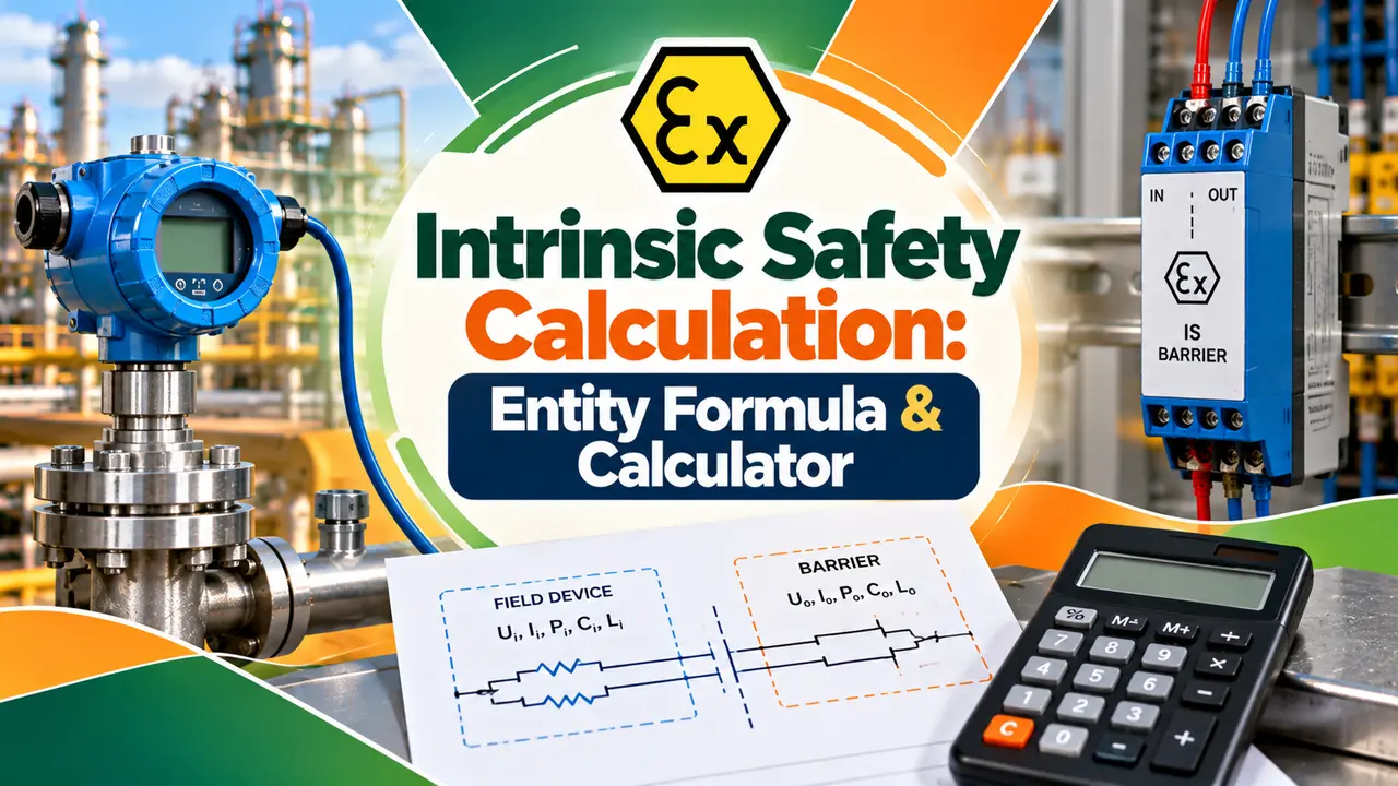
Intrinsic safety calculation is the check that a barrier or isolator, a certified field device and the cable between them cannot release enough energy to ignite a gas, by comparing their entity parameters. The loop is safe when Uo ≤ Ui, Io ≤ Ii, Po ≤ Pi, and the device plus cable capacitance and inductance stay within the Co and Lo allowed by the barrier.
- Voltage: Uo of the barrier ≤ Ui of the field device
- Current: Io ≤ Ii, and power: Po ≤ Pi
- Capacitance: Ci + Ccable ≤ Co
- Inductance: Li + Lcable ≤ Lo
- Unknown cable: use 200 pF/m and 1 µH/m as defaults
Intrinsic safety is one of several protection methods, and our comparison of explosion proof vs intrinsically safe instruments explains when it is the better choice. The zone and gas group used in the calculation come from the hazardous area classification drawing.
Entity Parameters: Uo, Io, Po, Co and Lo
The associated apparatus, a barrier or isolator in the safe area, is certified with output values: Uo, Io, Po, Co and Lo. The intrinsically safe apparatus in the field is certified with input values: Ui, Ii, Pi, Ci and Li.
| Barrier Output | Field Device Input | Rule | Meaning |
|---|---|---|---|
| Uo, maximum voltage | Ui | Uo ≤ Ui | Device withstands the fault voltage |
| Io, maximum current | Ii | Io ≤ Ii | Device withstands the fault current |
| Po, maximum power | Pi | Po ≤ Pi | No overheating inside the device |
| Co, allowed capacitance | Ci + Ccable | Ci + Cc ≤ Co | Stored electric energy stays safe |
| Lo, allowed inductance | Li + Lcable | Li + Lc ≤ Lo | Stored magnetic energy stays safe |
American labels often show the same values as Voc, Isc, Ca and La on the barrier and Vmax, Imax, Ci and Li on the device, as Macromatic explains. The rules do not change, only the symbols.
Gary Friend of Extech stresses that Uo, Io and Po are the maximum outputs under fault conditions, not the normal operating values. That is why an intrinsic safety calculation can never use the 24 V supply or the 20 mA signal in place of them.
Simple apparatus such as a thermocouple, RTD or switch needs no certificate. An Endress+Hauser control drawing defines it as a device that does not generate more than 1.5 V, 100 mA or 25 mW, or a passive part dissipating no more than 1.3 W.
Cable Capacitance and Inductance Values
The cable is the part most often forgotten, yet it can store more energy than the transmitter. A Turck declaration cites EN 60079 14, section 16.2.2, which allows 200 pF/m and 1 µH/m to be used for cable capacitance and inductance.
IEC 60079 25 allows the same defaults for two or three core conventional cables, or an L/R ratio instead, as quoted on the Control.com forum. Measured values from the cable datasheet are better, and Extech uses a typical 95 nF/km in its example.
Lcable = length × inductance per metre
300 m × 200 pF/m = 60000 pF = 60 nF
300 m × 1 µH/m = 300 µH = 0.30 mH
Lmax length = (Co minus Ci) ÷ C per metre
Use a screened twisted pair as described in shielded cable and twisted pair, and record the cable type and length in the instrument cable schedule so the intrinsic safety calculation can be repeated after any rerouting.
Count the full route length from the barrier terminals to the device, including spare loops in the marshalling cabinet and junction box. A few extra metres coiled in a tray still add capacitance.
The 1 % Rule for Combined L and C
When both a lumped capacitance and a lumped inductance are present, the stored energies can combine. A Pepperl+Fuchs control drawing states that Co and Lo are reduced to 50 % when both Ci and Li of the external circuit exceed 1 % of Co and Lo.
Intrinsic Safety Calculation Solved Example
Take a 28 V shunt diode barrier with 300 Ω, so Io = 28 ÷ 300 = 93 mA, and certificate values for Group IIC Ex ia of Co = 83 nF and Lo = 4.2 mH, the same Co and Lo used in the Extech example. The transmitter certificate in this example shows Ui 30 V, Ii 100 mA, Pi 0.75 W, Ci 10 nF and Li 0, with 300 m of cable.
Io 93 mA ≤ Ii 100 mA: pass
Po = 28 × 0.093 ÷ 4 = 0.65 W ≤ Pi 0.75 W: pass
C: 10 + 60 = 70 nF ≤ 83 nF: pass
L: 0 + 0.30 = 0.30 mH ≤ 4.2 mH: pass
Max length by C = (83 minus 10) × 1000 ÷ 200 = 365 m
The loop is safe with 300 m, but capacitance limits it to 365 m. In most IIC loops capacitance, not inductance, sets the maximum cable length, which is why the gas group matters so much.
Intrinsic Safety Calculation Calculator
The calculator applies the 1 % rule automatically. Pair it with our HART loop voltage budget calculator, because the barrier resistance that keeps the loop safe also drops volts at 20 mA.
IS Loop Calculation With a Higher Li Device
Now replace the transmitter with a device whose certificate shows Ci 10 nF and Li 0.5 mH, on the same barrier. Both are above 1 % of Co and Lo, so the allowed values halve.
1 % of Lo = 0.042 mH, Li = 0.5 mH: above
Allowed Co = 41.5 nF, allowed Lo = 2.1 mH
Max length by C = (41.5 minus 10) × 1000 ÷ 200 = 157 m
Max length by L = (2.1 minus 0.5) × 1000 ÷ 1 = 1600 m
Max cable = 157 m, so 300 m now fails
The same 300 m route that passed with a transmitter fails with this device. This is a very common surprise during revamps, and only a fresh intrinsic safety calculation will catch it.
Zener Barrier vs Galvanic Isolator
Zener diodes, a resistor and a fuse clamp voltage and current, and the fuse must be replaced if it blows.
An active, isolated circuit limits energy without depending on the IS earth and gives higher terminal voltage.
Extech warns in capital letters that using Zener barriers without an IS earth is not safe, so check the earthing in process plants before choosing them. The working of the diode itself is covered in what is a Zener diode, and the isolator approach in galvanic isolation.
Extech also notes that isolators give more voltage at the terminals and allow longer cables, while most 4 to 20 mA isolators pass HART.
Extech reports that the allowed Co for a 28 V Group IIC barrier changed from 130 nF to 83 nF after an IEC change. Plants built between 1995 and 2002 may still hold loop files based on the older value.
How Zone and Gas Group Change the Result
The gas group sets how much energy is allowed, so Co and Lo grow from IIC to IIB to IIA. In the Extech example the same 28 V loop allows 83 nF in IIC but 650 nF in IIB, so capacitance stops being a limit.
Protection level matters too, because Ex ia uses a safety factor of 1.5 on cable parameters while Ex ic does not. Extech shows the same loop rated Ex ic for Zone 2 allowing about 2.5 km of cable, and temperature class, covered in temperature classes in hazardous areas, must still match the gas.
Intrinsic Safety Calculation in 7 Design Steps
Attach the final sheet to the instrument loop diagram, so the maintenance team can see the limits before swapping any device. Certificate types and markings are explained in ATEX and IECEx.
Common Mistakes and Myths
- Barrier and device certificates are for the same gas group or better.
- Uo, Io and Po of the barrier are not above Ui, Ii and Pi.
- Cable capacitance and inductance use datasheet values or the defaults.
- The 1 % rule has been checked when the device has both Ci and Li.
- IS earth exists and is tested if Zener barriers are used.
- Quick to apply with certificate data.
- Lets you mix devices from many makers.
- Easy to audit and repeat later.
- Needs exact certificate values.
- Default cable values can be very cautious.
- Multiple channel loops need a system method.
For fieldbus segments use FISCO or the newer Ethernet APL approach instead of a device by device check. Our pages on Foundation Fieldbus and Ethernet APL explain those system level methods.
Extech Guide: How to Calculate an IS Loop Approval PDF
Video: Intrinsic Safety System Concept
Intrinsic Safety Calculation FAQ
Compare the barrier outputs Uo, Io and Po with the device inputs Ui, Ii and Pi, and each output must be equal or lower. Then add the cable capacitance and inductance to the device values.
The totals must stay within the Co and Lo of the barrier. If any one of the five checks fails, the loop is not intrinsically safe as designed.
The entity concept lets you connect certified devices from different makers by comparing their published parameters. The barrier gives output limits and the field device gives input limits.
Because each device is certified on its own, no combined system certificate is needed for a simple loop. You only need a documented intrinsic safety calculation for each loop.
EN 60079 14 allows a default of 200 pF per metre and 1 µH per metre for the cable. These values are cautious, so real cables usually allow longer runs.
If you have the cable datasheet or a measured value, use it instead. Record the value and its source on the intrinsic safety calculation sheet for later audits.
Subtract the device Ci from the barrier Co and divide by the cable capacitance per metre. Repeat the same step for inductance using Lo, Li and the cable inductance per metre.
The shorter of the two results is the maximum length. In Group IIC loops the capacitance limit is usually the one that decides it.
A Zener barrier limits energy with diodes, a resistor and a fuse, and it relies on a good IS earth. An isolator separates the circuits galvanically and does not need that earth.
Isolators cost more but give more voltage at the field and longer cables. Many new projects choose them for HART loops and for plants with poor earthing.
Related Articles
- Explosion Proof vs Intrinsically Safe Instruments
- Hazardous Area Classification Zones
- Temperature Classes in Hazardous Areas
- What Is Galvanic Isolation
- Difference Between ATEX and IECEx
External References
- How to Calculate an Intrinsically Safe Loop Approval, Gary Friend, Extech
- Understanding Entity Parameters, Macromatic
- Intrinsic Safety, Wikipedia
What We Learn Today
- Intrinsic safety calculation compares barrier Uo, Io and Po with device Ui, Ii and Pi, then adds cable capacitance and inductance to the device values.
- When the cable is unknown, 200 pF/m and 1 µH/m are the accepted defaults, and capacitance usually sets the maximum length in Group IIC.
- If both Ci and Li exceed 1 % of Co and Lo, the allowed values halve, so a device swap can make a safe loop unsafe.