
Level transmitter calibration verifies and corrects the relationship between process level and 4-20 mA output across the full range.
A 5-point calibration checks accuracy at 0%, 25%, 50%, 75%, and 100% of span to confirm linearity, not just the endpoints.
This guide covers the complete level transmitter calibration procedure including as-found documentation, adjustment, as-left verification, and the 5-point calibration table format used in industrial plant records.
Level transmitter calibration at five points confirms accuracy across the full range. A transmitter with a non-linear error at 50% passes a 2-point check but gives wrong readings in service.
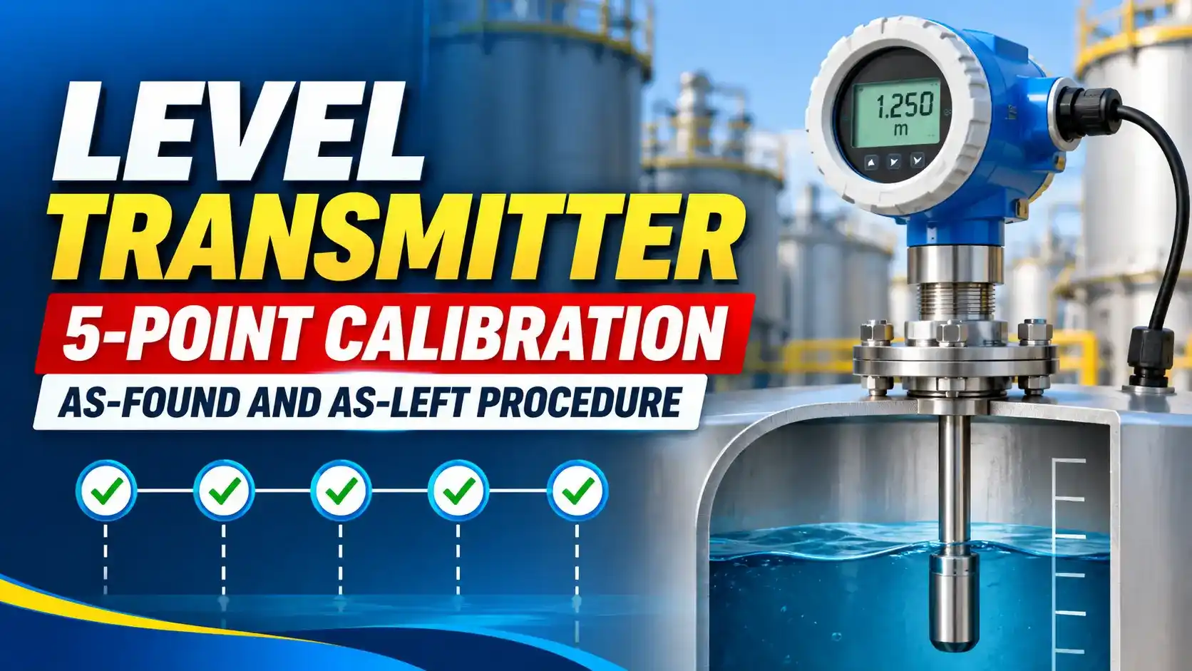
Level Transmitter Calibration: Why 5 Points Matter
A level transmitter outputs 4 mA at 0% of span and 20 mA at 100%. A correct reading at both endpoints does not guarantee linearity at midrange.
A 5-point calibration catches linearity errors by checking at five equally spaced inputs: 0%, 25%, 50%, 75%, and 100%.
Three terms must be understood before starting: as-found, as-left, and acceptable error limit. Click any term to expand.
Before You Start: Equipment and Preparation
Level transmitter calibration requires a calibration source to simulate the measured variable, a reference standard to measure the output, and the calibration record form. The specific calibration source depends on the transmitter technology.
| Transmitter Type | Calibration Source (Input) | Output Measurement |
|---|---|---|
| DP transmitter (differential pressure level) | Precision hand pump or dead-weight tester applying known differential pressure equal to the level span | Calibrated digital multimeter or loop calibrator measuring mA |
| Guided wave radar (GWR) | Physical level reference in the vessel or calibration chamber, or manufacturer configuration software with empty and full reference points | HART communicator reading PV or mA at the transmitter |
| Ultrasonic level transmitter | Known physical distance from the sensor face to the process surface (use a tape measure and reference reflector) | Calibrated mA meter or HART communicator |
| Capacitance level transmitter | Calibration cup filled to known levels, or manufacturer wet calibration procedure using the actual process fluid | Calibrated mA meter |
| Float or displacer | Known weights applied to simulate buoyancy forces at defined level points (dry calibration) or physical fill to defined levels (wet calibration) | Calibrated mA meter |
5-Point Level Transmitter Calibration Procedure
Expected mA at Each Calibration Point
25% span: 4 + (25/100) × 16 = 8.00 mA
50% span: 4 + (50/100) × 16 = 12.00 mA
75% span: 4 + (75/100) × 16 = 16.00 mA
100% span: 4 + (100/100) × 16 = 20.00 mA
Error% = (Actual mA minus Expected mA) / 16 × 100
Acceptable: Error% within plus or minus 0.5% of span (equals plus or minus 0.08 mA)
5-Point Calibration Table Format
| % Span | Applied Input | Expected mA | As-Found mA | As-Found Error% | As-Left mA | As-Left Error% | Pass/Fail |
|---|---|---|---|---|---|---|---|
| 0% | LRV (e.g. 0 mmH2O) | 4.00 | Record here | Calculate | Record here | Calculate | P/F |
| 25% | 25% of span | 8.00 | Record here | Calculate | Record here | Calculate | P/F |
| 50% | 50% of span (midpoint) | 12.00 | Record here | Calculate | Record here | Calculate | P/F |
| 75% | 75% of span | 16.00 | Record here | Calculate | Record here | Calculate | P/F |
| 100% | URV (e.g. 1000 mmH2O) | 20.00 | Record here | Calculate | Record here | Calculate | P/F |
Level Transmitter Calibration Calculator
Watch: Level Transmitter Calibration Procedure
Level Transmitter Calibration Questions
External References
- Level Transmitter Calibration Procedure | InstrumentationTools
- Calibration Procedures for Level Measurement Devices | Automation Forum (updated 2025)
What We Learn Today
- Level transmitter calibration at 5 points (0%, 25%, 50%, 75%, 100%) verifies linearity across the full span, not just at the endpoints
- As-found: record before any adjustment. As-left: record after adjustment and re-verification. Both are required in the calibration record.
- Expected mA at each point: 4 mA (0%), 8 mA (25%), 12 mA (50%), 16 mA (75%), 20 mA (100%)
- Acceptable error limit: typically plus or minus 0.5% of span, equal to plus or minus 0.08 mA on a 16 mA span
- An out-of-tolerance as-found result requires a non-conformance report and investigation before adjustment. Do not simply adjust and close the record.
- For DP type level transmitter calibration, the applied input pressures at each calibration point come from the hydrostatic head calculation for the specific vessel and fluid