The tachometer working principle turns rotation into pulses or a voltage that electronics convert into revolutions per minute. We compare each sensing method, work through a real gear tooth example and fix readings that jump.
A tachometer measures shaft speed by counting pulses per revolution or by reading a voltage that rises with speed. Below you will find the tachometer working principle for every common type, with a solved example and field fault finding.

What is the tachometer working principle and how is RPM calculated?
Tachometer working principle is simple: a sensor turns each shaft revolution into a fixed number of pulses, or into a voltage proportional to speed, and the electronics convert that into RPM. For pulse sensors, RPM = 60 × f ÷ PPR, where f is pulse frequency in Hz and PPR is pulses per revolution. Example: a magnetic pickup facing a 34 tooth gear reading 836 Hz gives 60 × 836 ÷ 34 = 1475.3 RPM.
What Is the Tachometer Working Principle?
The tachometer working principle is to convert shaft rotation into an electrical quantity, either a pulse train whose frequency is proportional to speed or a voltage proportional to speed. The instrument then scales that signal into RPM using the known pulses per revolution or the generator constant.
- Pulse types use RPM = 60 × f ÷ PPR, where PPR counts teeth, magnets or reflective marks per turn.
- Tacho generators give V = Kv × N, so voltage rises in a straight line with speed.
- Low speed needs the period method, because a few pulses in a fixed gate make the display jump.
Wikipedia records that Bryan Donkin described an early tachometer to the Royal Society of Arts in 1810. The modern tachometer working principle is the same idea, only the sensing is now electronic.
How Does a Tachometer Measure RPM?
A tachometer measures RPM by detecting a repeating feature on the shaft, counting how often it passes per second, then multiplying by 60 and dividing by the features per turn. Analog types skip counting and read a generated voltage instead.
In the common industrial setup a sensor faces a steel gear, and each passing tooth produces one pulse. A 34 tooth gear therefore gives 34 pulses per turn.
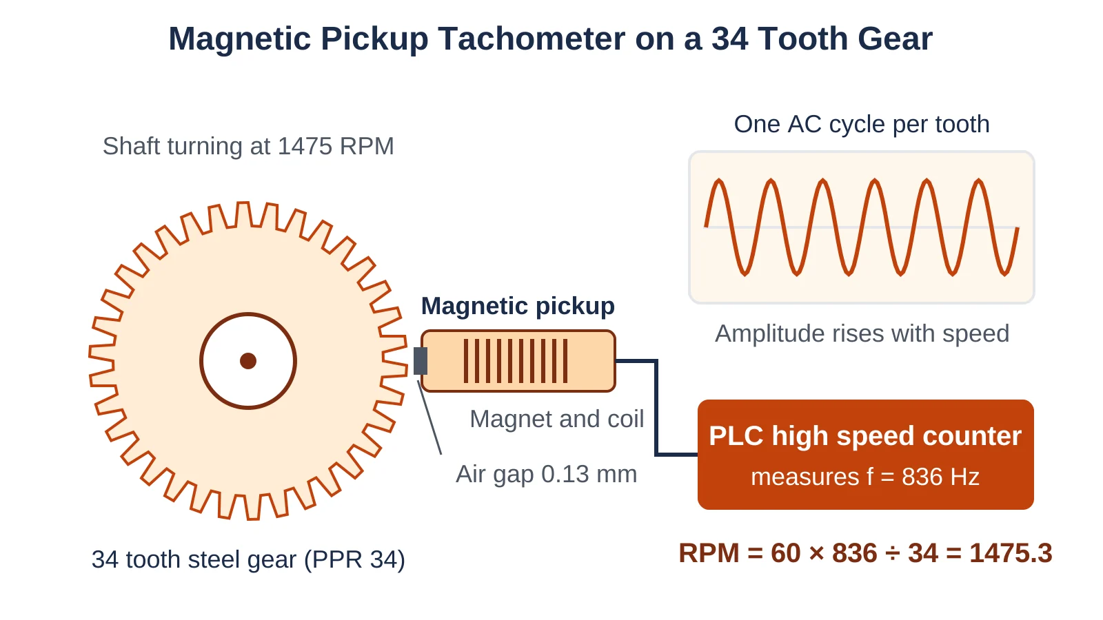
A comparator with a Schmitt trigger and proper hysteresis turns a noisy sine into clean square pulses, so small spikes do not become extra counts. In a PLC the pulses go to a fast input like those used in PLC high speed counter encoder applications, because ordinary inputs filter out short pulses.
What Are the Types of Tachometers?
Tachometers are grouped by how they sense rotation: contact, optical or laser, magnetic pickup, Hall effect, eddy current and tacho generator. Each type follows the same tachometer working principle but differs in power needs, low speed ability and mounting.
A rubber tip or wheel on the shaft drives an internal encoder.
A photodetector sees one pulse per reflective mark.
Magnet and coil sense ferrous teeth and generate AC.
Powered chip gives square pulses even near zero speed.
High frequency field senses a notch once per turn.
Small generator gives voltage proportional to speed.
Optical units work like an IR sensor with emitter and receiver and share electronics with retro reflective photoelectric sensors. RS Components notes a typical handheld laser tachometer reads from about 1 to 2 metres away.
The magnetic pickup applies Faraday law of electromagnetic induction, since each tooth changes the magnetic path and induces a voltage in the coil. Red Lion states in its pickup manual that this output is directly proportional to speed.
A Hall sensor needs a supply but gives a clean edge at any speed, so it suits zero speed switch applications. Read how a Hall effect sensor works and match the NPN or PNP output type to the input card.
A tacho generator shows the simplest tachometer working principle, V = Kv × N. For example, a unit rated 20 V per 1000 RPM gives about 29.5 V at 1475 RPM, and its polarity shows direction.
A high frequency oscillator drives an eddy current probe, which senses the gap to a keyway or notch, giving one pulse per turn. API 670 machinery protection systems use these probes for speed and overspeed on large compressors and turbines.
An AC tacho generator has a rotating magnet and a fixed winding, so both its voltage and frequency rise with speed. It has no brushes, but it cannot show direction the way a DC unit does.
With a stroboscope, start above the expected speed and come down slowly. The highest flash rate showing one frozen image is the true speed, because half that rate also freezes it.
How to Calculate RPM from Pulse Frequency
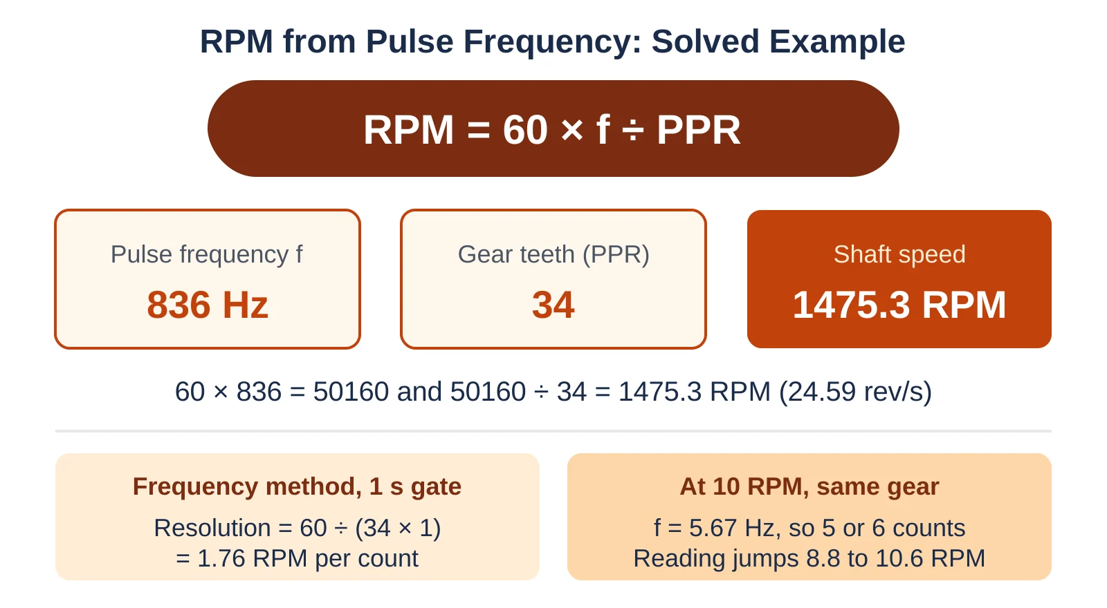
To calculate RPM, multiply the pulse frequency in Hz by 60 and divide by the pulses per revolution. For every pulse sensor, the tachometer working principle comes down to this one formula.
Gear teeth PPR = 34
Measured f = 836 Hz
60 × 836 = 50160
50160 ÷ 34 = 1475.3 RPM
Shaft frequency = 836 ÷ 34 = 24.59 rev/s
Resolution at 1 s gate = 60 ÷ (34 × 1) = 1.76 RPM per count
The result suits a 4 pole motor on 50 Hz, which runs below 1500 RPM because of induction motor slip. If the gear sits after a belt drive, apply the ratio with the pulley speed calculator.
Resolution shows how many RPM one extra pulse is worth, and a longer gate or more teeth improves it. A longer gate also slows the display update, so balance it against what the control loop needs.
The reverse form helps during design. At 3000 RPM the same gear gives 3000 × 34 ÷ 60 = 1700 Hz, so check that the sensor and counter input are rated above that frequency.
A 60 tooth gear is popular because pulse frequency in Hz then equals shaft speed in RPM. Red Lion rates its pickups against a 60 tooth reference gear.
Frequency Method vs Period Method for Low Speed
The frequency method counts pulses in a fixed gate and suits high speed, while the period method times the gap between pulses and suits low speed. Good digital tachometers switch between the two automatically.
At 10 RPM the 34 tooth gear gives 5.67 Hz, so a 1 s gate catches 5 or 6 pulses and the display flips between 8.8 and 10.6 RPM. The period method measures 0.1765 s between pulses and returns a steady 10.0 RPM.
- Simple on any counter card
- Stable at medium and high speed
- Predictable update rate
- Best resolution at low speed
- Sensitive to uneven tooth spacing
- Needs a timeout to show zero
If the PLC only offers gate counting, add teeth instead of time. A 120 tooth target at 10 RPM gives 20 counts per second, which is 0.5 RPM per count.
Contact vs Non Contact Tachometer: Which One to Choose?
Choose a contact tachometer for quick checks on an exposed shaft, and a non contact type for permanent, guarded or very fast machines. The table below matches each tachometer working principle to plant duties.
| Application | Recommended type | Reason |
|---|---|---|
| Handheld motor check | Laser or contact | Portable, no wiring |
| Steam turbine speed | Magnetic pickup or eddy current | Robust, API 670 systems |
| Slow conveyor | Hall or inductive proximity | Clean pulses near zero speed |
| Speed with direction | Quadrature Hall or encoder | Two channels give sense |
| Belt line speed | Contact wheel | Reads m/min directly |
An inductive proximity sensor sensing a few bolt heads is often the cheapest permanent choice. Where position also matters, compare incremental and absolute encoders.
Surface speed uses v = π × D × N, so a 0.1 m wheel at 1475 RPM reads about 463 m/min. Our sensor selection criteria guide covers temperature, oil mist and vibration checks.
Pulse scaling is the same idea used in turbine flow meters, so try the K factor calculator. It also fits the elements of a mechatronic system where sensors feed controllers.
Why Is My Tachometer Reading Wrong or Jumping?
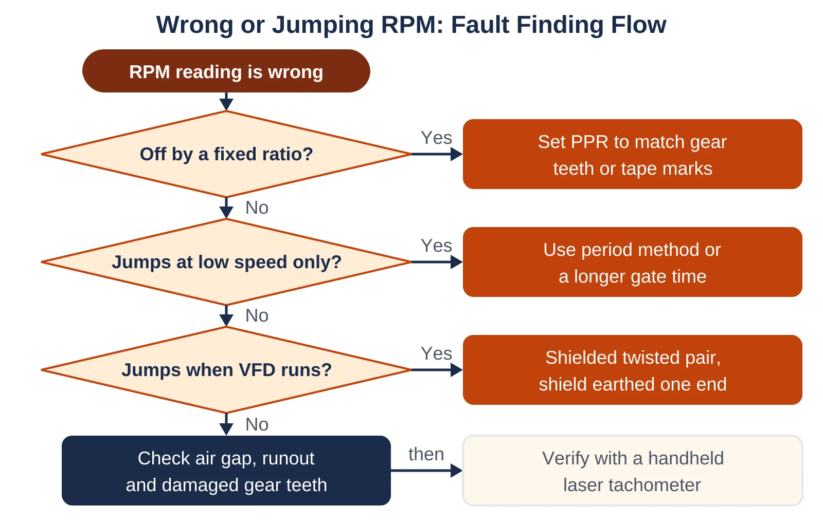
A wrong reading usually comes from a PPR mismatch, a poor air gap, electrical noise or the counting method at low speed. Follow the flowchart from the top to find the fault.
| Symptom | Likely cause | Field fix |
|---|---|---|
| Off by a fixed ratio | Wrong PPR entered | Count teeth, correct scaling |
| Reads double | Two pulses per mark | Matt background behind tape |
| Jumps when drive starts | Cable noise | Shielded twisted pair |
| Zero at low speed | Air gap too large | Reset gap to maker value |
| Spike once per turn | Damaged tooth or runout | Inspect gear |
Use shielded twisted pair cable, earth the shield at one end per our grounding techniques guide, and route it away from cables in PLC to VFD wiring. A cathode ray oscilloscope quickly shows missing or doubled pulses.
- Confirm PPR against counted teeth or marks.
- Set the air gap and lock the nut.
- Check shaft runout.
- Match NPN or PNP output to the card.
- Compare with a handheld laser unit.
The bulletin gives threshold speeds for a 0.005 inch gap, about 0.13 mm. It lists the MP 62TA reaching 1 V peak at 50 RPM on a 60 tooth gear, so you can see how weak the signal is at low speed.
How to Install a Magnetic Pickup Speed Sensor
Align the pickup square to the tooth centre, set the air gap with a feeler gauge and lock it. Once the gap is locked, the tachometer working principle stays reliable under vibration.
Speed often feeds trip logic too, so see vibration switch machine protection and our vibration sensor guide.
Tachometer Working Principle FAQ
The tachometer working principle is converting rotation into pulses or a voltage proportional to speed. The electronics then scale it into RPM.
For example, a 34 tooth gear reading 836 Hz gives 60 × 836 ÷ 34, which equals 1475.3 RPM on the display.
Multiply the pulse frequency in Hz by 60 and divide by pulses per revolution. A 60 tooth gear reading 1200 Hz therefore turns at 1200 RPM.
With one reflective mark the PPR is one, so 25 Hz means 1500 RPM. Always confirm the PPR before trusting the number.
A contact tachometer touches the shaft with a rubber tip or wheel, while a non contact type uses light, magnetism or eddy currents. Both end up counting pulses per revolution.
Contact units also measure surface speed in metres per minute. Non contact units are safer on guarded or very fast machines.
At low speed very few pulses fall inside the counting gate, so one extra pulse changes the reading a lot. A 34 tooth gear at 10 RPM gives only 5 or 6 counts per second.
Switch to the period method or add more teeth. The display will then settle to a steady value.
A Hall effect or inductive proximity sensor is best because it gives full height square pulses at any speed. A magnetic pickup output becomes too small at very low speed.
Use a target with several teeth or bolt heads. Combine it with the period method for fast and stable readings.
Related Articles
- Zero Speed Switch Working
- How a Hall Effect Sensor Works
- Incremental vs Absolute Encoders
- PLC High Speed Counter with Encoder
- Inductive Proximity Sensor Selection
External References
- Red Lion: Magnetic Pickups and In Line Preamplifier Bulletin (PDF)
- RS Components: A Complete Guide to Tachometers
- Wikipedia: Tachometer
What We Learn Today
- The tachometer working principle converts shaft rotation into pulses or a proportional voltage, and pulse types calculate speed using RPM equals 60 times f divided by PPR.
- Magnetic pickups are passive but weak at low speed, while Hall and inductive sensors give clean square pulses down to near zero speed for conveyors.
- Jumping or wrong readings usually come from wrong PPR scaling, gate counting at low speed, drive noise on unshielded cables, or a poorly set air gap.