
Nearly every pump, fan, and compressor motor in a plant traces back to a single steel enclosure full of starters and breakers, and understanding how this lineup is built is essential for anyone maintaining that equipment.
A motor control center is a modular steel enclosure that groups multiple motor starter units, called buckets, into one assembly fed from a common incoming bus, simplifying both wiring and maintenance for dozens of motors at once.
This builds on motor starting methods and motor protection relays, both of which live inside the buckets described here.
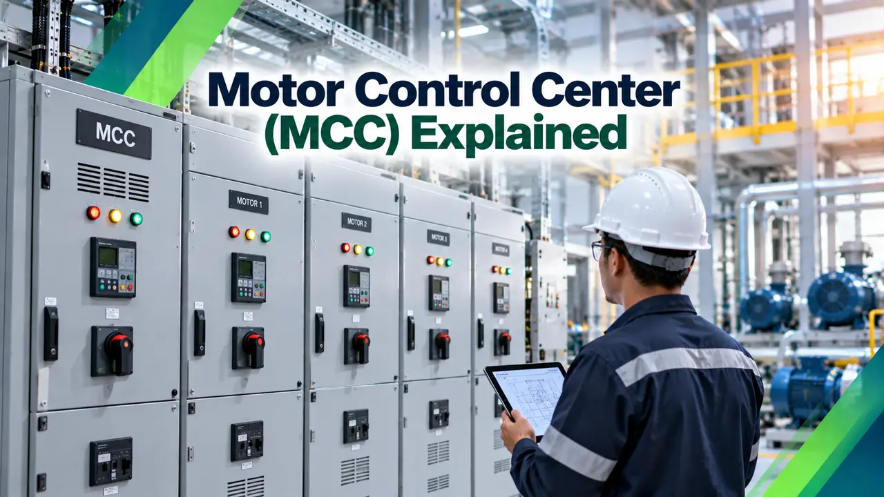
What Is a Motor Control Center
A motor control center is an assembly of one or more enclosed vertical sections, each holding a common power bus and a set of removable or fixed compartments called buckets.
Every bucket contains the components needed to start, run, and protect one motor, typically a contactor, an overload relay, fuses or a circuit breaker, and sometimes a small controller or VFD.
Incoming power arrives at a single main breaker, feeds a vertical bus running the height of each section, and distributes down to every bucket connected to that section.
Why Plants Standardize on This Design
Grouping dozens of motor starters into a single lineup means one incoming feed, one set of protective devices to coordinate, and one physical location for operators and technicians to check during a fault.
Without this consolidation, each motor would need its own separate enclosure, feeder cable, and disconnect, multiplying both installation cost and the number of places a fault could originate.
Anatomy of a Bucket
| Bucket Type | Typical Use | Key Component |
|---|---|---|
| Full voltage non reversing | Simple pumps and fans | Single contactor |
| Full voltage reversing | Conveyors, valve actuators | Two interlocked contactors |
| Reduced voltage starter | Large motors needing soft starting | Star delta or soft starter module |
| Variable frequency drive | Motors needing speed control | Integrated VFD unit |
Bus Structure and Power Distribution
A vertical bus runs the full height of each section, carrying power from the horizontal main bus at the top down to every bucket stacked in that column.
Bus bracing and short circuit ratings must match the maximum available fault current at the installation, since an undersized bus can fail catastrophically during a severe fault rather than simply tripping a breaker.
Grounding and Bonding Requirements
A continuous ground bus running the length of the lineup, bonded to every section's frame and to each bucket's chassis, gives fault current a low impedance path back to the source.
Without solid grounding, a fault inside one bucket can raise the enclosure to a dangerous touch voltage rather than tripping the protective device quickly, turning a contained fault into a serious shock hazard.
Main Breaker and Feeder Sizing
The main incoming breaker or fused switch must be sized for the sum of connected motor loads plus reasonable diversity, not simply added up worst case, since not every motor runs simultaneously at full load.
A poorly sized main device either nuisance trips under normal starting current or fails to protect the bus during an actual fault, so this calculation deserves careful attention during design.
Selecting and Sizing a Lineup
Draw Out vs Fixed Mounted Buckets
A draw out bucket can be racked out from its compartment while the vertical bus stays energized behind a safety shutter, letting a technician remove and replace a failed unit with minimal downtime.
A fixed mounted bucket is bolted permanently in place and wired directly, which costs less initially but requires the whole section to be de energized for any repair or replacement work.
Plants running continuous processes, where an unplanned motor outage is expensive, often justify the extra cost of draw out construction purely on the reduced repair time it offers.
Documenting the Lineup for Future Work
A single line diagram showing every section, bucket, and its connected motor, kept current as changes are made, saves enormous time during troubleshooting and future expansion planning.
Recording each protective device's actual settings alongside its coordination study results means a technician replacing a tripped relay years later can restore the exact same protection scheme without guesswork.
Ventilation, Heat, and Enclosure Ratings
Every contactor, overload relay, and VFD inside a bucket generates heat, and a lineup with too many high load buckets in a small room can quickly exceed its rated operating temperature.
Enclosure ratings such as NEMA 1 for indoor clean areas or NEMA 12 for dusty environments determine how much natural ventilation is even possible, which in turn affects how densely buckets can be packed.
Forced air cooling or a dedicated air conditioned electrical room becomes necessary once VFD content in a lineup grows large enough that passive ventilation alone cannot keep components within their rated temperature range.
Working With Reduced Voltage and VFD Buckets
A large motor started direct on line can draw six to eight times its rated current for a few seconds, stressing the bus and upstream transformer if too many start together.
Reduced voltage starters and VFD buckets limit this inrush, but they also take up more physical space and cost more per unit than a simple contactor and overload combination.
Motor Control Center vs Individual Starters
Centralized Lineup
One location, shared bus, easier coordination, but a single point of failure for many motors.
Individual Starters
Distributed risk and simpler single circuits, but far more wiring, space, and maintenance points.
Most industrial plants favor the centralized lineup for anything beyond a handful of motors, accepting the single point of failure in exchange for dramatically simpler installation and maintenance.
Routine Maintenance and Inspection
Thermal imaging surveys, usually conducted annually while the equipment is energized and under load, catch loose connections and overheating components long before they cause an unplanned trip.
Torque checking bus connections during a planned outage, using the manufacturer's specified values, prevents the loosening that thermal cycling naturally causes in bolted joints over years of operation.
Keeping a spare bucket of each common type on hand dramatically reduces downtime when a unit does eventually fail, since a spare can often be swapped in well under an hour.
Standards Governing Design and Installation
In North America, NEMA ICS 18 and UL 845 set construction and testing requirements for a motor control center, covering everything from bus bracing to bucket interlocking.
Internationally, IEC 61439 2 covers low voltage switchgear and controlgear assemblies more broadly, with specific provisions that a manufacturer must satisfy before labeling equipment compliant for a given fault current rating.
Specifying the correct standard early in a project avoids a costly mismatch discovered only after equipment has already been ordered and delivered to site.
Arc Flash Considerations
Every section of a modern lineup requires an arc flash hazard label showing the incident energy level, required personal protective equipment, and safe approach boundaries for anyone working nearby.
Calculating these values typically follows the IEEE 1584 methodology, factoring in available fault current, clearing time of upstream protective devices, and the physical working distance from the equipment.
Common Mistakes to Avoid
Upgrading an Aging Lineup
A facility running decades old equipment often faces a choice between full replacement and a targeted retrofit that swaps only the most obsolete buckets while reusing the existing bus and enclosure.
Retrofit kits from several manufacturers allow a modern bucket, complete with electronic overload protection and communication capability, to be installed into an older frame without replacing the entire lineup.
This approach usually costs a fraction of full replacement while still delivering the improved protection and diagnostic visibility that a fully modern system provides.
Watch: How a Motor Control Center Works
Motor Control Center FAQs
Related Articles on This Site
- Motor Starting Methods Compared
- Motor Protection Relay Types
- Circuit Breaker Coordination and Selectivity
- Busbar Sizing Calculation Guide
- Thermal Overload Relay Explained
External References
What We Learn Today
- This kind of lineup groups many motor starters into one enclosure fed from a shared bus.
- Each bucket holds a contactor, overload relay, and protective device for one motor.
- Bus sizing, protective coordination, and ventilation planning are the most common design pitfalls.