
DCS network redundancy means building the plant communication network so one broken cable or one dead switch never stops data from reaching the controllers and operator screens.
In this guide, we explain ring, star, and dual network designs in plain, simple language, so both students and working engineers can understand which one fits a real plant.
DCS network redundancy is the practice of adding a second, alternate communication path in the plant network, so that if one cable, switch, or port fails, the system automatically switches to the backup path and data keeps flowing without stopping the process.
DCS Network Redundancy: How this is Useful in Plants
A DCS is only as strong as the network carrying its data. Controllers, I/O racks, operator stations, and historians all talk to each other over this network, every single second.
If that network breaks even for a short time, operators can lose their view of the process. Alarms may not reach the control room. That is a serious risk in any running plant.
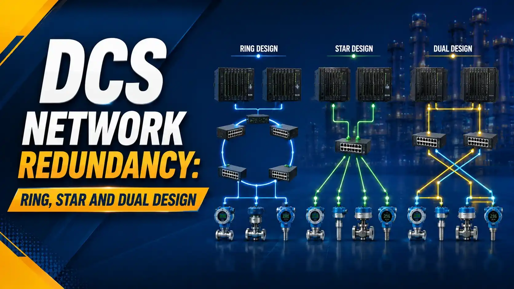
DCS network redundancy solves this by giving the network more than one path. If one path fails, the other one takes over automatically, and the plant keeps running safely.
This is different from controller redundancy, which we covered in our DCS controller redundancy guide. Controller redundancy protects the brain of the system.
Network redundancy protects the nervous system that carries signals to and from that brain, much like the broader DCS platform described in our distributed control system overview.
Three Common Network Architectures in a DCS
Most plant networks are built using one of three basic shapes. Each shape has its own way of surviving a fault.
Ring
Switches form a closed loop. A break heals itself because data can flow the other way around.
Star
Every device connects to one central switch. Simple to wire, but that center switch is a single point of failure.
Dual (Redundant Star)
Two central switches, and every device is wired to both. Losing one switch does not blind the network.
Ring Topology: Data Can Travel Two Ways
In a ring, switches are connected one after another, and the last switch connects back to the first one. This forms a closed loop.
Under normal working, one link in the ring is usually held back to stop data loops. If a cable breaks, a redundancy protocol opens that reserve link within milliseconds, and data starts flowing the other way around the ring.
Ring designs are popular in DCS and SCADA networks because they need less cable than a star, especially when equipment is spread across a large plant area, as covered in our network switches in SCADA and DCS guide.
Star Topology: Simple, But Watch the Center
In a star, every switch or device connects directly to one central switch. Wiring is easy to understand and easy to troubleshoot.
The problem is that central switch. If it fails, every device connected to it loses contact with the rest of the network, all at once.
A plain star is fine for small, non-critical parts of a network, similar to the ES/OS/AS layers we describe in our DCS components guide. It is rarely used alone for the core DCS backbone.
Dual Network: Two Independent Paths at Once
A dual, or redundant star, network uses two separate central switches instead of one. Every field switch and workstation connects to both of them.
Under normal conditions, both paths can carry live data, or one stays as a hot backup, depending on how the vendor designs it. Either way, one switch can fail completely, and the network keeps working through the other one.
This is the design most DCS vendors recommend for the plant backbone, because it removes the single point of failure a plain star still has, according to this overview of DCS network architectures and protocols.
It also pairs well with the cyber-security segmentation ideas in our air-gapped vs segmented ICS networks guide, and with the broader defenses covered in our SCADA network security guide.
Comparing the Three Architectures at a Glance
| Feature | Ring | Star | Dual (Redundant Star) |
|---|---|---|---|
| Single point of failure | No, if protocol is active | Yes, the center switch | No, two center switches |
| Cable usage | Low | Medium | High |
| Typical recovery time | Milliseconds to a few hundred ms | None, network stays down | Very fast, often near-zero |
| Best fit | Spread-out field areas | Small, non-critical zones | Core DCS backbone |
| Wiring complexity | Medium | Low | High |
How a Ring Actually Detects and Fixes a Break
A ring network needs a protocol running on the switches to manage the reserved link and to detect a break. Common examples are RSTP, MRP, and HSR.
Each switch sends short test signals to its neighbours. When a cable breaks, a switch stops receiving these signals from one side.
The protocol then opens the previously blocked link, and the ring becomes one long line instead of a loop. Data reaches every switch again, just by a different path.
According to this explanation of the Media Redundancy Protocol under IEC 62439-2, the standard defines fixed recovery classes, but the real recovery time in a working ring still depends on how many switches sit between the fault and the point of detection.
Try It: Ring Network Recovery Time Calculator
This calculator gives a simple estimate of how long a ring network takes to heal itself after a cable break, based on the number of switches and typical per-switch processing delay.
Let Us Take an Example
Take a ring with 12 switches. The link failure detection time is 10 ms, and each switch adds 1.5 ms of relearn delay when the ring reconfigures.
Number of Switches = 12
Per-Switch Delay = 1.5 ms
Step 1: Switch Delay Total = 12 × 1.5 = 18 ms
Step 2: Recovery Time = 10 + 18 = 28 ms
28 milliseconds is faster than a human eye can even notice. That is why a well-designed ring can survive a cable break without the operator screen freezing or the controller losing contact with the field.
A Simple Way to Choose the Right Network Design
Map the plant layout first
Note how far apart the field switches, control room, and racks are, before picking a shape.
Protect the core backbone with a dual design
Use a redundant star or dual-ring for the main path between controllers and operator stations.
Use ring segments for spread-out field areas
A ring saves cable when equipment is scattered across a large outdoor area.
Reserve plain star only for small, non-critical zones
Use it where a short outage would not affect the running process.
Pick a redundancy protocol that matches your switches
Check that RSTP, MRP, or HSR support matches across every switch brand used in the ring.
Test the failover during commissioning
Pull a cable on purpose and time the actual recovery, instead of trusting the datasheet alone.
Good Practices for DCS Network Redundancy
✓ Do
- Keep the ring or dual-star protocol version identical across all switches
- Route the two redundant cable paths through different physical routes
- Document which link is the reserved link in every ring segment
- Test failover recovery time during commissioning, not just design review
✗ Don't
- Run both redundant cables through the same tray or duct
- Mix incompatible ring protocols from different switch vendors
- Assume a plain star is fine for the core DCS backbone
- Skip periodic testing of the redundant path once it is commissioned
Worth Reading if You Want to Go Deeper
Questions Students and Technicians Often Ask
External References
- Perle: Ring Protocol MRP (IEC 62439-2)
- mfgtechhub.com: DCS Architecture, Network Topologies and Protocols
What We Learn Today
- DCS network redundancy adds a backup communication path so one cable or switch failure never stops the network.
- Ring topology heals itself quickly and uses less cable, star topology is simple but has a single point of failure, and dual network architecture removes that single point of failure entirely.
- A worked example showed a 12-switch ring recovering in about 28 milliseconds, using a simple detection-time-plus-switch-delay model.
- Most DCS backbones use a dual, redundant design, with ring segments reserved for spread-out field areas.