
A battery or 24 V supply connected the wrong way round can destroy regulators, capacitors and microcontrollers within milliseconds. A small reverse polarity protection stage at the input stops that damage while wasting very little power in normal operation.
Swapped supply wires are one of the most common field mistakes in automotive, battery and industrial 24 V equipment. The right protection circuit blocks reverse current with the lowest possible voltage drop and heat.
What Is Reverse Polarity Protection?
Reverse polarity protection is any circuit that stops current from flowing backwards through electronics when the supply is connected with plus and minus swapped. Without it, the body diodes of ICs and polarised capacitors conduct heavily, as explained in diode types explained.
Monolithic Power Systems lists reverse polarity among the classic automotive power disturbances, together with load dump, voltage sags and negative pulses. A wrong jumper cable connection during a jump start is the typical real world cause.
Industrial panels face the same risk whenever a technician rewires a field device or replaces a power supply. A single wrong connection on a shared 24 V bus can damage many devices at once.
How a Reversed Supply Damages a Board
Electrolytic and tantalum capacitors are especially vulnerable, because reverse voltage breaks down their oxide layer. A reversed tantalum capacitor can fail short and burn even at a few volts.
Regulator ICs usually have internal ESD and substrate diodes from ground to input, so a reversed input drives large current straight through the chip. Our comparison of linear vs switching regulators explains why both types need protection upstream.
Many PLC digital input cards accept a reversed 24 V supply without damage, because the maker already built in reverse polarity protection. Always check the datasheet rather than assuming every device survives a wiring mistake.
6 Proven Reverse Polarity Protection Circuits
A silicon diode in the positive line.
Lower drop Schottky diode in series.
Reverse biased diode across the input with a fuse.
PMOS in the positive line, gate to ground.
NMOS in the ground return.
IC with charge pump driving an N channel FET.
Each method trades cost, voltage drop, power loss and fault behaviour differently. The sections below explain how each circuit behaves in normal and reversed connection.
Series Diode and Schottky Diode
A diode in series with the positive line conducts in normal use and blocks when the supply is reversed. The onsemi note puts the drop at about 0.7 V for a standard silicon diode and as low as 0.3 V for a Schottky diode.
The drop wastes power equal to load current times forward voltage, and it also lowers the voltage reaching the load. Schottky diodes cut that loss but leak more at high temperature, as covered in Schottky diode advantages and limitations.
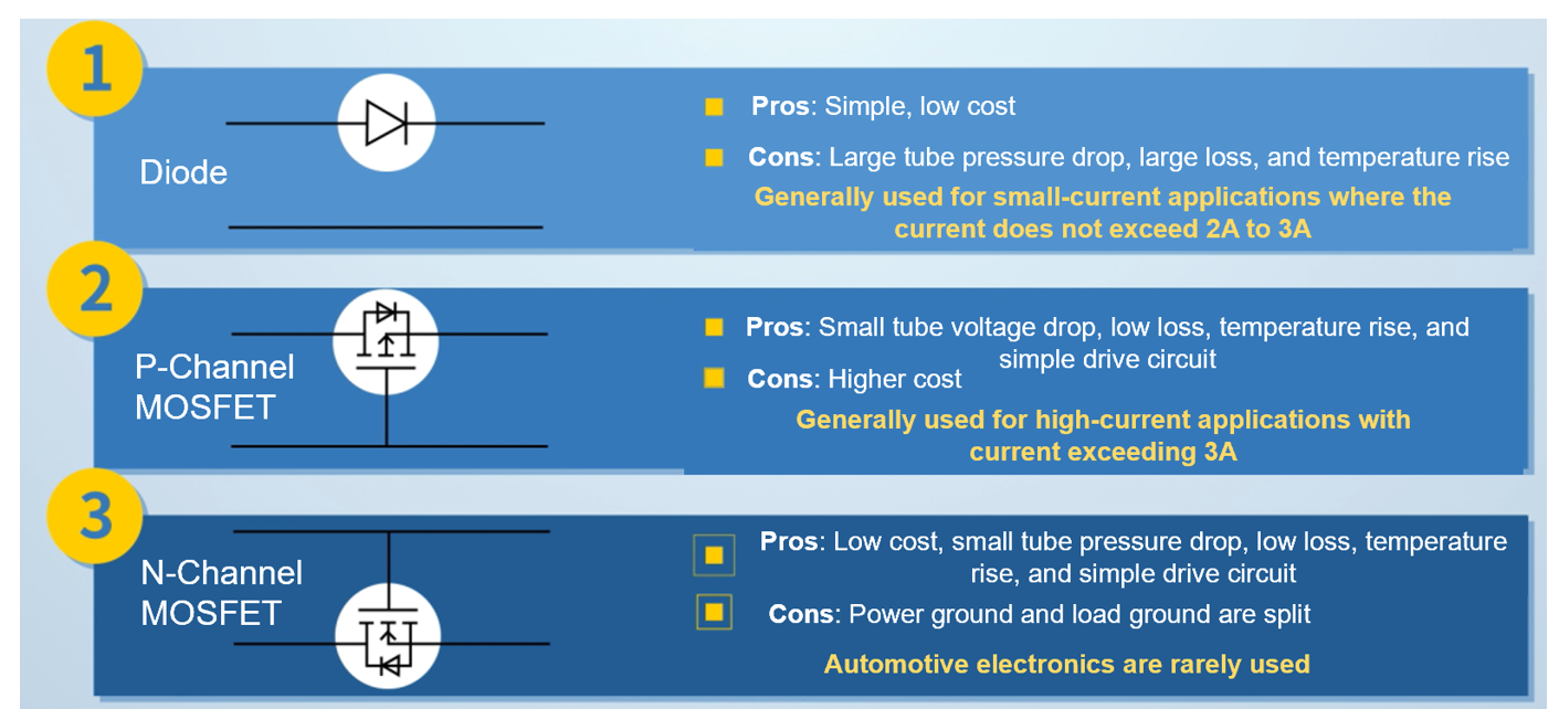
Monolithic Power Systems notes that series Schottky diodes are typically used for low current loads of about 2 to 3 A. Above that level, the diode heat quickly becomes hard to manage on a small board.
When a diode must survive a reversed battery, pick one with a reverse voltage rating at least twice the supply. A 40 V Schottky on a 12 V line leaves margin for spikes and jump start events.
Shunt Diode with Fuse
In this method a diode sits across the input, reverse biased in normal operation, so it adds no series drop. When the supply is reversed the diode conducts heavily and blows a fuse placed ahead of it, sized using our fuse selection guide.
The circuit is cheap and efficient, but it needs a fuse replacement after every mistake. The diode must also survive the full fault current until the fuse clears, so its surge rating matters more than its average rating.
P Channel MOSFET on the High Side
A P channel MOSFET placed in the positive line with its gate pulled toward ground turns fully on when the supply is correct. With reversed input the gate to source voltage has the wrong sign, so the channel stays off and the body diode is reverse biased, as explained in MOSFET working principle.
A Zener diode and resistor clamp the gate to source voltage, because 24 V systems exceed the usual 20 V gate rating. Monolithic Power Systems suggests a high side P channel MOSFET once load current rises beyond about 3 A.
The onsemi note explains that hole mobility is roughly 2.5 times lower than electron mobility. A P channel device therefore needs a larger die than an N channel device for the same on resistance, which raises cost at high current.
A P channel protection FET is connected with its drain toward the supply and its source toward the load, which looks backwards at first sight. That orientation lets the body diode conduct at power up until the channel turns on.
N Channel MOSFET on the Low Side
An N channel MOSFET can sit in the ground return, with its gate tied to the positive input. It is cheaper and has lower on resistance, but it lifts the board ground away from the supply ground by the small channel drop.
That floating ground is a problem for communication ports and shared sensor returns, so Monolithic Power Systems notes it is rarely used in automotive designs. It suits simple standalone loads where no other circuit references the battery negative.
Ideal Diode Controller ICs
An ideal diode controller drives an N channel MOSFET in the positive line using an internal charge pump, because the gate must rise above the source. The onsemi note points out that this driver adds cost and complexity, similar to the drivers in MOSFET gate driver ICs.
The Texas Instruments LM74700 Q1 is a well known example that regulates the MOSFET drop to about 20 mV and turns it off quickly when current reverses. It also blocks reverse current during input dropouts, which a simple P channel circuit cannot do.
| Method | Typical Drop at 5 A | Blocks Reverse Current | Relative Cost |
|---|---|---|---|
| Silicon diode | 0.7 to 1.0 V | Yes | Very low |
| Schottky diode | 0.3 to 0.5 V | Yes, some leakage | Low |
| Shunt diode and fuse | Fuse drop only | Blows fuse | Very low |
| P channel MOSFET | I × Rds on | Only reversed supply | Medium |
| N channel low side | I × Rds on | Only reversed supply | Low |
| Ideal diode controller | About 20 mV regulated | Yes, fast | Higher |
The last column shows why simple diodes stay popular for small loads. At several amperes, however, the power saved by a MOSFET based reverse polarity protection circuit usually pays for the extra parts.
Power Loss Formula for Diode and MOSFET
MOSFET loss = I² × Rds on
Efficiency of stage = (1 minus Vdrop ÷ Vsupply) × 100
Example: 12 V supply, 5 A load
Schottky Vf = 0.5 V, MOSFET Rds on = 10 mΩ
Diode loss = 5 × 0.5 = 2.50 W
MOSFET loss = 5² × 0.010 = 0.25 W
Diode 95.83 percent, MOSFET 99.58 percent
The diode loss grows linearly with current, while the MOSFET loss grows with the square of current from a very low starting point. At light loads they are close, but at 5 A the MOSFET wastes ten times less heat in this example.
Reverse Polarity Protection Loss Calculator
Use the hot Rds on value from the datasheet, which can be about 1.5 times the room temperature figure. Use the diode forward voltage at your actual current, not the lowest value on the first page.
Second Example: 24 V Industrial Controller
A 24 V controller drawing 2 A through a Schottky diode with a 0.45 V drop wastes 0.9 W, which a small SMA package can struggle to dissipate. The same load through a 20 mΩ P channel MOSFET wastes only 0.08 W.
In a 24 V PLC system the lower drop also leaves more headroom when the supply sags. That matters for panels powered through long cables or by ageing power supplies.
Automotive 12 V and 24 V Reverse Battery Tests
ISO 16750 2 defines electrical loads for road vehicle equipment, including a reverse voltage test. Commonly used values are 14 V reversed for 12 V systems and 28 V reversed for 24 V systems, applied for about 60 s.
Monolithic Power Systems also describes the supply dropout test from the same standard, where a P channel circuit stays on and lets output capacitors discharge back into the input. Ideal diode controllers avoid this backflow, and a TVS diode still handles load dump transients.
Place the TVS diode before the protection MOSFET when you need to clamp reversed transients too. Check that it is bidirectional or that reverse conduction is taken care of by the fuse.
Choosing the Right Reverse Polarity Protection Circuit
Protection circuits often sit next to redundant PLC power supplies, where ideal diode ICs also combine two sources as diode ORing. After the protection stage, a buck converter usually steps the voltage down for logic circuits.
- Reverse voltage rating above the maximum reversed input.
- Gate to source voltage clamped below its rating.
- Hot Rds on or hot Vf used in loss calculation.
- Copper area enough to dissipate the loss.
- Capacitors placed after the blocking element.
- Reverse connection tested on a real prototype.
- Stops expensive damage from wiring errors.
- MOSFET methods waste very little power.
- Ideal diode ICs block backflow.
- Easy to add at the design stage.
- Diodes drop voltage and create heat.
- MOSFET circuits need gate protection.
- Controller ICs add cost and parts.
- Shunt methods need fuse replacement.
onsemi MOSFET Selection PDF
MOSFET Protection Circuit Video
Reverse Polarity Protection FAQ
It is a circuit at the power input that blocks current when the supply wires are swapped. It protects regulators, capacitors and ICs from the large reverse current that would otherwise flow.
Common methods use a diode, a MOSFET or an ideal diode controller IC. The choice depends mainly on load current, allowed voltage drop and cost.
A series diode is simple and reliable, but it drops about 0.3 to 0.7 V and wastes power as heat. At 5 A a Schottky with 0.5 V drop dissipates 2.5 W.
That heat needs board area or a heatsink, and the drop reduces headroom on low voltage rails. MOSFET based circuits cut this loss dramatically at higher currents.
With correct polarity the gate is pulled below the source, so the channel turns fully on and conducts with a tiny drop. With reversed polarity the gate voltage has the wrong sign and the channel stays off.
The body diode is also reverse biased in that case, so no current flows. A Zener diode clamps the gate on higher voltage systems.
Electrons are about 2.5 times more mobile than holes, so an N channel device gives lower resistance for the same die size. That makes it cheaper at high current.
However, the gate must be driven above the source, which needs a charge pump. Ideal diode controller ICs include that charge pump and extra protection features.
It sets electrical test conditions for road vehicle equipment, including a reverse voltage test. Common values are 14 V reversed for 12 V systems and 28 V reversed for 24 V systems.
The device must survive the test and often must work normally afterwards. Always read the exact test class agreed with the vehicle maker.
For a diode, multiply load current by forward voltage to get power loss in watts. For a MOSFET, multiply the square of current by the on resistance.
Always use the hot values from the datasheet for both parts, because resistance and drop change with temperature. The calculator above compares both reverse polarity protection methods and shows the efficiency of each stage.
Yes, a fuse still protects wiring against short circuits and component failures downstream of the protection stage. The MOSFET only handles the reversed supply case.
In shunt diode designs the fuse is part of the reverse polarity protection itself. It must blow quickly, before the diode is damaged by the full fault current from the battery.
Related Articles
- Schottky Diode Advantages and Limitations
- What Is a MOSFET
- TVS Diode Explained
- Fuse Selection Guide
- MOSFET Gate Driver ICs Explained
External References
- AND90146 MOSFET Selection for Reverse Polarity Protection, onsemi
- Designing a Reverse Polarity Protection Circuit, Part I, Monolithic Power Systems
- Power MOSFET, Wikipedia
What We Learn Today
- Reverse polarity protection blocks current when supply wires are swapped, using diodes, MOSFETs or ideal diode controller ICs at the power input.
- Diode loss equals current times forward voltage, while MOSFET loss equals current squared times on resistance, so MOSFETs win at higher currents.
- Automotive boards must pass ISO 16750 2 reverse voltage tests, and ideal diode controllers also block backflow during supply dropouts.