
Two switching thresholds instead of one turn a slow, noisy signal into a clean digital edge.
A Schmitt trigger is a comparator with two different switching thresholds, one for a rising input and one for a falling input. The gap between them, called hysteresis, stops noise from causing repeated false switching.
What Is a Schmitt Trigger?
A Schmitt trigger is a switching circuit that changes output state at an upper threshold when the input rises and at a lower threshold when the input falls. It is a special case of the comparator circuit with positive feedback added.
An ordinary comparator has only one threshold. When a noisy signal hovers near that point, the output chatters rapidly between high and low.
The circuit solves this by moving the threshold once the output switches. After switching high, the input must fall well below the original point before the output switches back.
Otto Schmitt invented the circuit in 1934 while studying nerve impulses. Today it appears inside logic gates, microcontroller inputs and almost every digital interface.
How Hysteresis Removes Noise
The difference between the two thresholds is the hysteresis window. Any noise smaller than this window cannot cause a false transition.
The same idea appears in mechanical devices as deadband, for example in pressure switch deadband. It prevents a pump or alarm from cycling on every small ripple.
3 Brilliant Hysteresis Circuit Designs
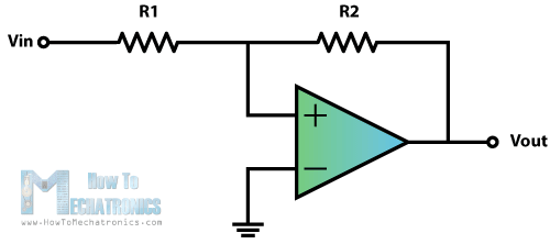
Resistors feed part of the output back to the non inverting input.
Two emitter coupled transistors share a resistor that creates hysteresis.
Chips like 74HC14 and CD40106 have Schmitt inputs built in.
The op amp version is the most flexible because resistor values set both thresholds. Our op amp basics guide explains the saturation voltages used in the calculation.
The 74HC14 hex inverter is the quickest practical option for digital work. Its thresholds are fixed by the chip and listed in the datasheet.
Inverting Schmitt Trigger Threshold Formula
Upper threshold UTP = β × Vsat
Lower threshold LTP = minus β × Vsat
Hysteresis = 2 × β × Vsat
Worked example:
R1 = 10 kΩ, R2 = 100 kΩ, Vsat = 12 V
β = 10 ÷ 110 = 0.0909
UTP = 0.0909 × 12 = 1.09 V
LTP = minus 1.09 V
Hysteresis window = 2.18 V
R1 is the resistor from the non inverting input to ground and R2 is the feedback resistor from the output. A larger R1 relative to R2 widens the hysteresis window.
For single supply circuits, add a reference voltage to shift both thresholds above ground. The TI reference design linked below shows the full method.
Schmitt Trigger vs Ordinary Comparator
| Feature | Comparator | Schmitt Trigger |
|---|---|---|
| Thresholds | One | Two |
| Feedback | None | Positive |
| Noise near threshold | Output chatters | Clean single switch |
| Slow input edges | Multiple transitions | One transition |
| Typical use | Level detection | Signal cleanup and debouncing |
Chatter is not only annoying but harmful. It can clock counters many times or make relays buzz and wear out.
Noise pickup is common in long industrial cables. Pair a Schmitt input with shielding and good layout, as covered in noise reduction for digital ICs.
Where Hysteresis Switching Is Used
A single 74HC14 gate plus a resistor and capacitor forms a square wave oscillator. It is a simple alternative to the 555 timer for low accuracy clocks.
Clean edges are essential before signals reach flip flops and counters. A single noisy edge can advance a counter several times.
Design Tips for Reliable Switching
Set the hysteresis window larger than the expected peak to peak noise, but small enough that real changes still switch the output. A window of 5 to 10 percent of the signal range is a good start.
Use rail to rail comparators when the output must swing close to the supply. Open drain comparators need a pull up resistor, which changes the high level used in the calculation.
Always simulate or test with a slowly changing input. It is the only way to confirm the thresholds on real hardware.
For microcontroller projects, check whether the input pins already include hysteresis. Many modern chips offer it as a configurable option, which can save an external gate and board space.
Hysteresis Threshold Calculator
This calculator assumes symmetrical output saturation. Use the real high and low output levels from the op amp datasheet for exact results.
- Strong noise immunity.
- Clean edges from slow signals.
- Simple to build.
- Built into many logic ICs.
- Small signals inside the window are ignored.
- Thresholds drift with supply on some chips.
- Adds a little delay.
- Needs design for single supply use.
TI Comparator With Hysteresis Reference Design
EEVblog Schmitt Trigger Tutorial Video
Schmitt Trigger FAQ
Related Articles
- Comparator Circuits Explained
- Op Amp Basics
- Digital Logic Gates Explained
- Astable vs Monostable vs Bistable Multivibrator
- 555 Timer IC Explained
External References
- Comparator with Hysteresis Reference Design, Texas Instruments
- What Is Schmitt Trigger, How To Mechatronics
- Hysteresis Comparator Calculator, All About Circuits
- Schmitt Trigger, Wikipedia
What We Learn Today
- Two thresholds and hysteresis stop noise from causing false switching.
- Positive feedback sets the thresholds in op amp designs.
- Logic ICs like 74HC14 give ready made Schmitt inputs for clean edges.