A drive that refuses to start is usually a wiring or input mode problem, not a faulty drive. This guide walks through every signal between the PLC and the VFD with real terminal data, a scaling calculator and a field troubleshooting table.
Good PLC to VFD wiring needs only a few signals, but each one has rules for voltage, polarity and shielding. We cover the terminal table, scaling math, Modbus option and a fault finding checklist.
What Is PLC to VFD Wiring?
PLC to VFD wiring is the set of control connections that lets a PLC start, stop, reverse and set the speed of a variable frequency drive, and read back its status and faults. A typical hardwired scheme uses two or three digital outputs, one analog output for the speed reference, and one or two digital inputs for the drive ready, running and fault signals.
- Run and direction: PLC digital outputs to drive digital inputs, usually 24 V DC
- Speed: PLC analog output, 4 to 20 mA or 0 to 10 V, to drive analog input
- Feedback: drive relay or transistor output to PLC digital input
- Match sinking and sourcing on both sides, or set the drive input jumper
- Use shielded twisted pair for analog and keep it away from motor cables
The control signals are low voltage, but they sit inside a panel full of fast switching power electronics. That is why a neat PLC to VFD wiring job is as much about routing and grounding as it is about terminal numbers, as we also see in field instrument to system cabinet wiring.
PLC to VFD Wiring Terminal Table
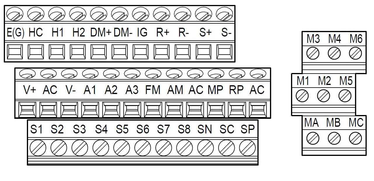
The table shows a common hardwired scheme for a PLC with 24 V DC I/O. Terminal names follow the INVT GD20 style, and other brands use the same signals under other names.
| Signal | PLC side | VFD side | Cable and notes |
|---|---|---|---|
| Run forward | Digital output, 24 V DC | S1 digital input set to forward run | Multicore, 0.5 to 0.75 mm² |
| Run reverse or direction | Digital output | S2 digital input set to reverse | Leave unwired if reverse is not allowed |
| External fault or interlock | Field contact or PLC output | S3 set to external fault or coast stop | Normally closed for fail safe action |
| Speed reference | Analog output, 4 to 20 mA or 0 to 10 V | AI2 with dip switch set to mA or V | Shielded twisted pair, shield at one end |
| Drive fault | Digital input | RO1 relay, 3 A at 250 V AC | Wire normally closed for wire break detection |
| Drive running | Digital input | RO2 relay or Y1 transistor | Confirms the drive accepted the run command |
| Network option | RS 485 port or Ethernet card | 485+ and 485 minus terminals | Modbus RTU with 120 Ω termination |
INVT lists the GD20 relay outputs at 3 A for 250 V AC or 1 A for 30 V DC, and notes they are not meant for high frequency switching. A relay contact is therefore fine for a fault signal to a PLC input, but not for pulse counting.
Run, Stop and Direction Inputs
Control.com explains that in two wire control the drive runs while the signal is present, while three wire control uses momentary start pulses and a normally closed stop input.
With a PLC, two wire control is the usual choice because the PLC itself holds the run logic and interlocks. The PLC simply keeps the run output on while all permissives are healthy, a pattern you can also see in PLC timer instructions used for start delays.
Never use the drive keypad stop as your only safety stop. Emergency stops belong in a hardwired safety circuit or the drive Safe Torque Off input, which INVT and others wire as a redundant normally closed pair.
Sinking and Sourcing Between PLC and VFD
A sourcing output pushes current out of its terminal, and a sinking input accepts current into its terminal. In PLC to VFD wiring both ends must form one complete loop, so a sourcing PNP output must drive a sinking input, as explained in sinking and sourcing in PLC.
INVT states that the GD20 digital inputs accept 12 to 30 V, have an internal impedance of 3.3 kΩ and select PNP or NPN with a U shaped jumper, with PNP as the default. Industrial Monitor Direct also lists the selection points for other brands, such as parameter 10.03 on the ABB ACS580 and jumper SW1 on the Schneider Altivar 320.
- Common in Europe and in IEC style panels
- A shorted signal wire to 0 V turns the input off, which fails safe
- Works with drives set to PNP or source mode
- Easy to test with a meter between output and 0 V
- Common on Japanese and many North American drives
- Needs the drive input set to NPN or sink mode
- A wire touching 0 V can switch the input on
- Mixing with a PNP drive input simply never works
Industrial Monitor Direct warns that the drive internal 24 V jumper may need removing when a PLC output drives the input, or the two supplies can back feed. Read about 24 volts in PLC systems before you design the commons.
Analog Speed Reference: 4 to 20 mA or 0 to 10 V
The speed reference is the most sensitive part of PLC to VFD wiring. INVT specifies its AI2 input as 0 to 10 V or 0 to 20 mA by dip switch, with 20 kΩ input impedance on voltage and 500 Ω on current, so the PLC output card must be able to drive that load.
Current is usually the better choice in a noisy panel or over long runs, because a 4 to 20 mA loop ignores voltage drop and shows a broken wire as a reading below 4 mA. Our article on why 4 to 20 mA is used instead of voltage explains this in detail.
Current loop with a live zero for wire break detection.
Simple voltage signal that picks up noise on long wires.
Bipolar voltage where the sign sets direction.
Speed sent as a number over Modbus or PROFINET.
Current signal = 4 + 16 × r mA
Voltage signal = 10 × r V
PLC raw count = r × full scale count
Solved Example: Scaling the Speed Reference
A pump drive is set for 0 Hz at minimum and 50 Hz at maximum reference, and the PLC must ask for 37.5 Hz. The PLC is a Siemens style card where 4 to 20 mA equals 0 to 27648 counts.
Current = 4 + 16 × 0.75 = 16.00 mA
Voltage = 10 × 0.75 = 7.50 V
Raw count = 0.75 × 27648 = 20736
If a series meter shows 16.00 mA but the drive shows another frequency, the drive input scaling is wrong. Cross check the count with our free PLC raw count calculator before you go to site.
Shielding and Routing Rules for VFD Control Cables
Yaskawa India advises shielded twisted pair for control wiring, with the shield grounded to the drive ground terminal and control cables kept apart from main circuit wiring. It also says not to use control wiring longer than 50 m when the analog frequency reference comes from a remote source.
INVT also says motor, input power and control cables must be routed separately. Our guide on shielded cable and twisted pair explains how each layer rejects noise.
- Analog reference in its own shielded twisted pair, never shared with digital signals
- Shield landed at one end only, as the manual says
- Control cables cross motor cables at 90 degrees, never run in parallel in the same tray
- Ferrules on every stranded core
- No ground loop current flowing in the shield
Yaskawa recommends stripping about 5.5 mm of insulation when no ferrule is used, and says not to solder the core wire.
How to Connect a PLC to a VFD Using Modbus
Many drives offer a built in RS 485 port, so the PLC can send run commands and the speed reference as Modbus registers. This cuts the cable count to one shielded pair and gives you current, power, fault codes and run hours without extra I/O, as described in Modbus protocol explained.
Many plants keep the run permissive and fault hardwired and use Modbus only for data. When the link drops, Modbus RTU troubleshooting helps.
Set the drive communication timeout and action, so that a lost Modbus link stops the motor or holds a safe speed. Without this setting, many drives keep running at the last speed after the PLC goes silent.
PLC to VFD Wiring Troubleshooting Table
Most faults after commissioning come down to five things: input mode, command source, scaling, noise and a missing common. Work through the table in order and you will clear most problems in PLC to VFD wiring without changing any hardware.
| Symptom | Likely cause | What to check |
|---|---|---|
| Drive ignores run command | Command source set to keypad or network | Run command source parameter set to terminals |
| Motor runs at minimum speed only | Reference source not set to analog input | Frequency source parameter and AI dip switch |
| Speed wrong at full signal | Drive AI scaling or max frequency mismatch | Drive AI min and max points and PLC scaling |
| Speed hunts by a few hertz | Noise or ground loop on analog cable | Shield grounding, cable route and twisted pair |
| Reading below 4 mA | Open loop or wrong card type | Loop continuity and AO card set to current |
| Random trips with PLC healthy | Overload or supply issue, not wiring | Drive fault log and motor current trend |
When the wiring checks out but the drive still trips, the cause is usually on the power side, which we cover in VFD overload trip causes. Harmonics and dips can also upset PLC inputs nearby, as explained in power quality issues with VFD and PLC.
Before writing the drive parameters, it is worth reading through VFD parameter configuration so the command source, reference source and ramp times match your PLC logic. The motor side also needs care, and a dv/dt filter may be needed on long motor cables.
PLC to VFD Wiring FAQ
Connect PLC digital outputs to the drive run and direction inputs, and a PLC analog output to the drive analog input for speed. Wire a drive relay output back to a PLC input so the program can see faults and running status.
Then set the drive command source and reference source to terminals. Finally match the PNP or NPN input mode to the PLC output card before testing.
Yes, almost every drive accepts a 0 to 10 V reference, and it works well for short runs inside one panel. It is simple to measure with any meter at the drive terminals.
For longer runs or noisy areas, choose 4 to 20 mA instead. A current loop ignores lead resistance and shows a broken wire as a value below 4 mA, which helps fault finding.
The most common reason is that the drive command source is still set to the keypad or to the network. The second reason is a polarity mismatch between a PNP output and an NPN input.
Measure the voltage at the drive input with the PLC output on and off. If the voltage never changes, check the common wiring and the input mode jumper.
In most PLC to VFD wiring the analog shield is grounded at one end only, usually where the drive or PLC manual says. This stops circulating earth current from flowing through the shield and into the signal.
Yaskawa asks for the shield to be landed on the drive ground terminal. Always follow the manual of the device you connect to, and never leave both ends floating.
A sourcing device pushes current out of its terminal, while a sinking device accepts current into it. A complete circuit needs one of each, so a PNP output must drive an input set to sink current.
Most drives let you change the input mode with a jumper or a parameter. INVT uses a U shaped jumper on the GD20, with PNP as the factory default setting.
Related Articles
- VFD Parameter Configuration
- Sinking and Sourcing in PLC
- PLC Analog Scaling and Raw Count
- Modbus RTU Troubleshooting
- VFD Sizing and Selection Guide
External References
- INVT GD20 EU Series VFD Manual
- Industrial Monitor Direct: Sourcing vs Sinking PLC and VFD Wiring
- Wikipedia: Variable frequency drive
What We Learn Today
- PLC to VFD wiring uses digital outputs for run and direction, an analog output for speed, and a relay input back to the PLC for faults.
- Sinking and sourcing must match on both sides, so set the drive PNP or NPN jumper or parameter to suit the PLC output card.
- Use shielded twisted pair for the speed reference, ground the shield at one end and route control cables away from motor cables.