
A normal PLC input misses pulses once they arrive faster than the scan, so encoder counts drift and positions go wrong. Dedicated counter hardware catches every edge in real time, independent of the program.
Encoders, flow meters and proximity sensors on gear teeth can produce thousands of pulses per second. Special counter inputs count them in hardware so the program only reads the result.
What Is a High Speed Counter?
A high speed counter is a hardware counting circuit inside a PLC or on a dedicated module that counts input pulses independently of the program scan. Ordinary CTU and CTD counters only see an input once per scan, so they miss fast pulses.
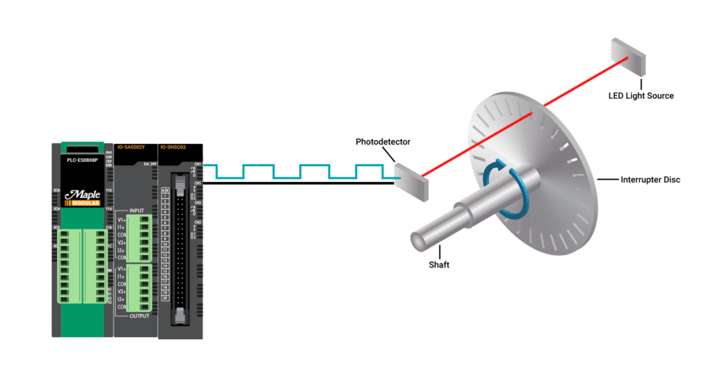
Maple Systems notes that high speed inputs usually accept up to about 100 kHz. Standard inputs often have millisecond filters that limit them to a few hundred hertz.
A scan based counter can only catch pulses slower than about half the scan rate. With a 10 ms scan cycle, that is only 50 Hz.
The counter value is read into a register the program uses like any other tag. Compare values and interrupts let the hardware act instantly when a count is reached.
Counting Modes
One pulse input, direction from a fixed setting.
One pulse input plus a direction input.
A and B channels, count on some edges.
Count every edge of A and B.
Maple Systems explains that quadrature encoders give A and B signals 90° apart, so the counter knows both count and direction. In x4 mode it adds four counts per encoder cycle.
An index or Z pulse arrives once per revolution and can reset or capture the count. It is used for homing machines.
How the Counter Handles an Encoder
Opto 22 describes the same quadrature decoding in its technical note on quadrature counters. The logic runs in hardware, so the program scan time does not matter.
Speed is found by taking the change in count over a fixed time. Many modules also provide a direct frequency mode for VFD speed feedback.
5 Practical High Speed Counter Setup Steps
Match sinking or sourcing encoder outputs to the input card, as explained in sinking and sourcing. Most industrial encoders use 24 V DC push pull outputs.
Noise causes extra counts, so route encoder cables away from motor leads and use shielded twisted pair cable.
Encoder Frequency Formula
Count rate = Input frequency × Multiplier
Example:
1024 PPR encoder at 3000 RPM
Input frequency = 1024 × 3000 ÷ 60 = 51.2 kHz
x4 decoding gives 204.8 k counts per second
51.2 kHz is inside a 100 kHz input limit
The input limit applies to the pulse frequency on each channel, not the multiplied count rate. Always check the datasheet definition.
If the frequency is too high, use a lower PPR encoder or a dedicated motion module.
Frequency Calculator
Leave at least 20 percent margin below the limit for overspeed and signal distortion on long cables.
- Counts independently of scan time.
- Accurate position and speed.
- Hardware compare outputs react instantly.
- Direction detection with quadrature.
- Noise creates false counts.
- Signal type must match the input.
- Counter rollover must be handled.
- Frequency limits vary by model.
When choosing hardware, list counter needs early, as advised in how to select the right PLC.
Opto 22 Quadrature Counter PDF
HSC Encoder Setup Video
High Speed Counter FAQ
Related Articles
- PLC Counter Instructions
- How the PLC Scan Cycle Works
- Sinking and Sourcing in PLC
- How to Increase PLC Speed
- Servo Motor vs Stepper Motor
External References
What We Learn Today
- A high speed counter counts pulses in hardware outside the scan.
- Quadrature modes give direction and up to 4 counts per cycle.
- Check frequency, signal type and wiring before commissioning.