
As coal units retire and inverter based solar and wind take over, grids lose the spinning machines that once held voltage and frequency steady. An old idea, a synchronous machine running with no load on its shaft, is now coming back to fill that gap.
A synchronous condenser is a synchronous machine that spins freely on the grid and trades only reactive power. It also adds real rotating inertia and fault current, which inverter based plants cannot easily provide.
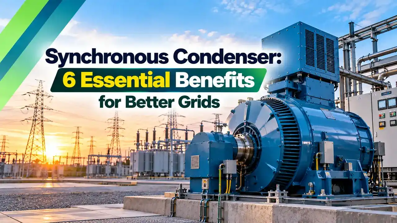
What Is a Synchronous Condenser?
A synchronous condenser is a synchronous machine connected to the grid with no mechanical load and no prime mover, used only to generate or absorb reactive power and to support voltage. It is built like the machine in synchronous motor working principle, but its shaft drives nothing.
Once running at synchronous speed, the machine draws only a small active power to cover its losses. By changing the DC field current, operators make it behave like a variable capacitor or a variable reactor, with smooth control in both directions.

The word condenser is the old name for a capacitor, because an overexcited machine looks like a capacitor to the network. Utilities used these machines widely before power electronics, and the idea is a close cousin of capacitor bank sizing for power factor correction.
How Excitation Controls Reactive Power
Field current above the unity level, internal EMF higher than grid voltage.
Internal EMF about equal to grid voltage, current at its minimum.
Field current below the unity level, internal EMF lower than grid voltage.
The field winding is fed by a static or brushless exciter controlled by an automatic voltage regulator, the same arrangement described in generator excitation system and AVR. The AVR raises field current when grid voltage sags and lowers it when voltage rises.
Reactive power, unlike active power, does no useful work but sets the voltage profile of the network, as explained in active, reactive and apparent power. A synchronous condenser lets a grid operator move that reactive power exactly where it is needed.
Because the machine is a real rotating mass locked to the grid, it responds to a voltage dip within the same cycle, with no control delay. Its stored kinetic energy also slows the fall of frequency after a large unit trips.
Reactive Power Formula for a Synchronous Condenser
With no shaft load, the load angle stays close to zero, so the reactive output depends mainly on the difference between internal EMF E and grid voltage V. In per unit, the simplified relation below is a good first estimate.
Q = reactive power output, MVAr
S = machine rating, MVA
V = grid voltage, per unit
E = internal EMF set by excitation, per unit
Xs = synchronous reactance, per unit
Example:
S = 100 MVA, V = 1.0, E = 2.2, Xs = 1.6
Q = 100 × 1.0 × (2.2 minus 1.0) ÷ 1.6
Q = 100 × 0.75 = 75.00 MVAr supplied
A positive answer means the machine supplies reactive power, and a negative answer means it absorbs it. Per unit values make such sums easy, as shown in per unit system in power systems.
Synchronous Condenser Reactive Power Calculator
Real machines also have field heating and stator current limits, so check the capability chart before promising full output. The simple formula ignores saturation and losses.
Reading the V Curves
A V curve plots armature current against field current at a fixed active power. For a synchronous condenser the active power is almost zero, so the curve is a sharp V with its lowest point at unity power factor.
Points to the right of the bottom are overexcited and points to the left are underexcited. The lines joining the bottoms of curves at different loads are called compounding curves, and on a condenser they stay close to the vertical axis.
6 Essential Benefits of a Synchronous Condenser
Short circuit strength matters because protection relays need enough fault current to detect a fault, and inverters typically limit their output close to rated current. Fault level studies follow the method in short circuit current calculation.
BHEL notes that existing power plants can be repurposed, reusing the generator, step up transformer, excitation and protection to save time and cost. Such conversion still needs a fresh generator synchronizing procedure once the turbine is decoupled.
Some converted hydro units can switch between generating and condensing modes. BHEL calls such a combined arrangement a hydrogenator plant.
Second Worked Example: Inertia and Fault Current
Inertia is expressed by the constant H, the stored kinetic energy divided by the machine rating. A 100 MVA machine with an assumed H of 1.5 seconds stores 150 MWs, and a flywheel that raises H by 3.5 times lifts it to 525 MWs.
For fault current, assume a subtransient reactance of 0.15 per unit. The initial fault contribution is about 1 ÷ 0.15 = 6.7 per unit, or roughly 6.7 times rated current, far more than a typical inverter supplies.
Real Synchronous Condenser Projects
ABB reports that Statkraft chose two high inertia synchronous condenser systems for the Lister Drive Greener Grid project in Liverpool, England. ABB states the 67 MVAr machine uses a 40 tonne flywheel and increases instantly available inertia by 3.5 times.
ABB also describes Lister Drive as the first high inertia configuration in the world, with earlier deployments in Australia, Canada and Scotland. The project supports National Grid in running a zero carbon electricity system.
In India, BHEL offers units of up to 300 MVAr at a maximum of 21 kV, with static excitation and starting by a static frequency converter. Large solar parks and HVDC terminals are typical places where such machines strengthen weak buses, and load flow analysis helps choose their location.
Selecting a Condenser for a Weak Grid
Planners judge grid strength with the short circuit ratio, the fault level at the connection point divided by the rating of the inverter plant or HVDC link. IEEE Std 1204 treats a ratio below 3 as low for HVDC terminals, and such weak buses often suffer voltage swings and control interactions.
The required machine rating comes from studies of fault level, reactive power range and inertia, not from a rule of thumb. Study engineers model the machine with its subtransient reactance, inertia constant and excitation limits, then test the worst contingency.
Condenser Versus STATCOM and Capacitor Banks
| Feature | Synchronous Condenser | STATCOM | Capacitor Bank |
|---|---|---|---|
| Reactive control | Smooth, both directions | Smooth, both directions | Steps, supply only |
| Output at low voltage | Rises with dip | Limited to rated current | Falls with V squared |
| Fault current | Several times rated | About rated | None |
| Inertia | Yes, real rotating mass | No, unless grid forming | No |
| Losses and maintenance | Higher, rotating parts | Lower, static | Lowest |
| Response | Instant, inherent | Very fast, controlled | Switching delay |
For an industrial plant that only needs power factor correction, an APFC panel is far cheaper. The synchronous condenser earns its place on transmission grids, where inertia and fault strength are the real problems.
- Adds inertia and fault current.
- Smooth reactive control in both directions.
- Strong overload capacity for seconds.
- No harmonics injected into the grid.
- Higher capital cost than static devices.
- Rotating parts need regular maintenance.
- Standing losses even at zero output.
- Needs a starting system and synchronising.
Operation, Starting and Maintenance
Large units are usually started by a static frequency converter, which runs the machine up to speed before it is synchronised, much like the method in alternator working principle. Smaller machines may start with a pony motor or as an induction motor on damper windings.
- Verify excitation and AVR limits before energising.
- Confirm lube oil and cooling systems are running.
- Check phase sequence and synchroscope before closing.
- Record vibration and bearing temperatures at speed.
- Test overexcited and underexcited capability limits.
- Confirm protection settings for loss of field and overcurrent.
Watch the underexcited limit closely during light load nights, when line charging raises voltage. Too little field current can push the machine toward pole slipping.
High voltage at night on long lightly loaded lines, described in Ferranti effect in transmission lines, is exactly when the synchronous condenser runs underexcited to absorb reactive power. Coordinate its relay settings with other protective relays on the bus.
BHEL Synchronous Condenser Brochure PDF
Grid Stability Machine Video
Synchronous Condenser FAQ
It is a synchronous machine running on the grid with no mechanical load and no prime mover. It exists only to supply or absorb reactive power and to support the grid voltage.
It also adds real rotating inertia and useful fault current to the network. These features have made it popular again in grids with high solar and wind.
Raising the field current makes the machine overexcited, so it supplies reactive power like a capacitor. Lowering the field current makes it underexcited, so it absorbs reactive power like a reactor.
An automatic voltage regulator adjusts the field current continuously. It keeps the bus voltage close to the operator set point as load and generation conditions change.
It plots armature current against field current while the active power is held constant. The lowest point of the V is at unity power factor, where armature current is smallest.
Moving right of the lowest point means overexcited operation that supplies reactive power with leading current. Moving left means underexcited operation that absorbs reactive power with lagging current.
Inverter based plants usually provide little inertia and limit their fault current near rated values. Retiring coal units remove the spinning mass that once held frequency and voltage steady.
A rotating condenser restores both inertia and short circuit strength on such weak buses. ABB reports a 3.5 times inertia boost at the Lister Drive project in Liverpool.
A STATCOM is a static power electronic device that controls reactive power very quickly. Its current is limited close to rating, and it has no real rotating mass to give inertia.
The rotating machine offers inertia, high fault current and short overloads. It needs more maintenance and has higher standing losses than the static device.
BHEL offers units of up to 300 MVAr each, at rated voltages of up to 21 kV for each machine. Both cylindrical rotor and salient pole designs are available from them.
ABB supplied a 67 MVAr high inertia unit with a 40 tonne flywheel for Lister Drive. Many projects install two or more machines for redundancy.
Large units are usually brought up to speed by a static frequency converter. The machine is then synchronised to the grid exactly like a generator would be.
Smaller machines may use a pony motor or start as an induction motor on their damper windings. After synchronising, the starting equipment is disconnected and the field takes over control.
Related Articles
- Synchronous Motor Working Principle
- Generator Excitation System and AVR
- Active, Reactive and Apparent Power
- Power Factor Correction Explained
- Short Circuit Current Calculation
External References
- Synchronous Condenser Brochure, BHEL
- Statkraft Lister Drive Project News, ABB
- Synchronous Condenser, Wikipedia
What We Learn Today
- A synchronous condenser is a synchronous machine with no shaft load that supplies reactive power when overexcited and absorbs it when underexcited.
- The V curve shows armature current against field current, with its lowest point at unity power factor and capacitive operation on the right side.
- Beyond reactive power, the machine adds real inertia and high fault current, which is why grids with large solar and wind shares are installing them.