
Loads change all day, and an automatic panel adds or removes capacitor steps so the power factor stays close to unity.
Automatic power factor correction switches capacitor banks in and out as the reactive demand of a plant changes. It avoids utility penalties, frees transformer capacity and lowers cable losses.

What Is an APFC Panel?
An APFC panel is an automatic power factor correction panel that measures the reactive power of a plant and switches capacitor steps to keep the power factor at a target, usually 0.95 to 0.99. It is the automatic version of a fixed capacitor bank.
Schneider Electric India describes it as a panel that switches capacitor banks automatically as the load changes. Better power factor lowers electricity costs and penalties.
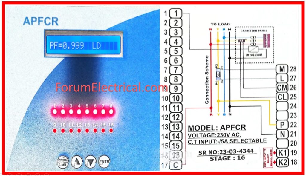
Inductive loads such as motors and transformers draw lagging reactive current. Capacitors supply this locally, as explained in power factor correction.
Reactive, active and apparent power are linked by the power triangle, covered in active, reactive and apparent power. The panel only changes the reactive side.
7 Essential APFC Panel Parts
The CT must see the load current plus the capacitor current, so it is installed upstream of the capacitor tap off. A wrong CT position is the most common reason a panel hunts or never switches, see CT working principle.
IEC 60831 requires capacitors to discharge to 50 V or less within about one minute. The relay therefore waits before reconnecting the same step.
How the Controller Switches Steps
Step ratios such as 1:1:2:2 or 1:2:4 give fine resolution with few steps. A 1:2:4 arrangement of 25 kVAR steps can cover 25 to 175 kVAR in 25 kVAR increments.
The controller also uses a time delay so it does not chase every short load swing. Faster control needs thyristor switching.
Contactor vs Thyristor APFC Panel
| Feature | Contactor Switched | Thyristor Switched |
|---|---|---|
| Response time | Seconds | About one cycle |
| Inrush on switching | High, needs damping contactors | Almost none, zero crossing |
| Wear | Mechanical contacts wear | No moving parts |
| Best for | Steady process loads | Welding, cranes, presses |
| Cost | Lower | Higher |
Schneider lists relay based, contactor based and thyristor based types, with thyristors used for rapidly fluctuating loads. The switching device itself is described in thyristor and TRIAC.
Where drives create harmonics, capacitors can resonate and fail. A 7 percent detuned reactor tunes the step near 189 Hz, below the 5th harmonic, as explained in power harmonics.
APFC Panel Sizing Formula
Worked example:
Load = 500 kW, PF from 0.75 to 0.95
tan φ1 = tan(arccos 0.75) = 0.882
tan φ2 = tan(arccos 0.95) = 0.329
kVAR = 500 × 0.553 = 276.6
Choose about 300 kVAR, for example 25 + 25 + 50 + 50 + 75 + 75
A small margin covers capacitor ageing and future load growth. Compare with the capacitor bank kVAR formula and the power factor improvement calculation.
Detuned capacitors must be rated for the higher voltage caused by the series reactor, often 440 V or 480 V units on a 415 V system.
Maintenance and Troubleshooting
Measure capacitor current every quarter and compare with the rated value. Falling current shows lost capacitance, while a high THD reading points to resonance risk.
APFC Panel kVAR Calculator
Round up to standard step sizes and add a margin of about 10 percent. Check the transformer and cable ratings before adding a large bank.
- Avoids low PF penalties.
- Frees transformer kVA.
- Lowers cable losses.
- Improves voltage.
- Harmonic resonance.
- Overcompensation to leading PF.
- Contactor wear.
- Capacitor overheating.
ABB Capacitor Bank Guide PDF
Automatic PF Correction Training Video
APFC Panel FAQ
Related Articles
- Power Factor Correction Explained
- Capacitor Bank Sizing
- Capacitor Bank kVAR Formula
- Power Factor, kW, kVA and kVAR
- Power Factor Improvement Calculation
External References
- Low Voltage Capacitor Banks, ABB
- Working Principle and Calculation, Schneider Electric
- Power Factor, Wikipedia
What We Learn Today
- The APFC panel switches capacitor steps to track changing reactive demand.
- CT position, step ratios and delays decide stable control.
- Use thyristors for fast loads and detuned reactors where harmonics exist.