
A current based overload relay only guesses how hot a motor is, and it can be fooled by blocked cooling, high ambient or slow running on a drive. Tiny PTC sensors buried in the windings measure the real temperature and trip the motor before the insulation is damaged.
Thermal overload relays model heat from current, but they cannot see a choked fan cowl or a hot pump room. PTC thermistors in the windings close that gap by reacting to the actual winding temperature.

What Is Motor Thermistor Protection?
Motor thermistor protection is a direct temperature protection scheme in which PTC thermistors embedded in the stator windings are monitored by a relay that trips the motor when the winding reaches its rated limit. Unlike a thermal overload relay, it measures heat where it is produced instead of estimating it from current.
A PTC thermistor has a low, fairly steady resistance until it nears its nominal response temperature, after which resistance rises very sharply. The basic physics of these sensors is covered in NTC and PTC thermistor working, and that steep rise is what makes a simple relay enough to read them.
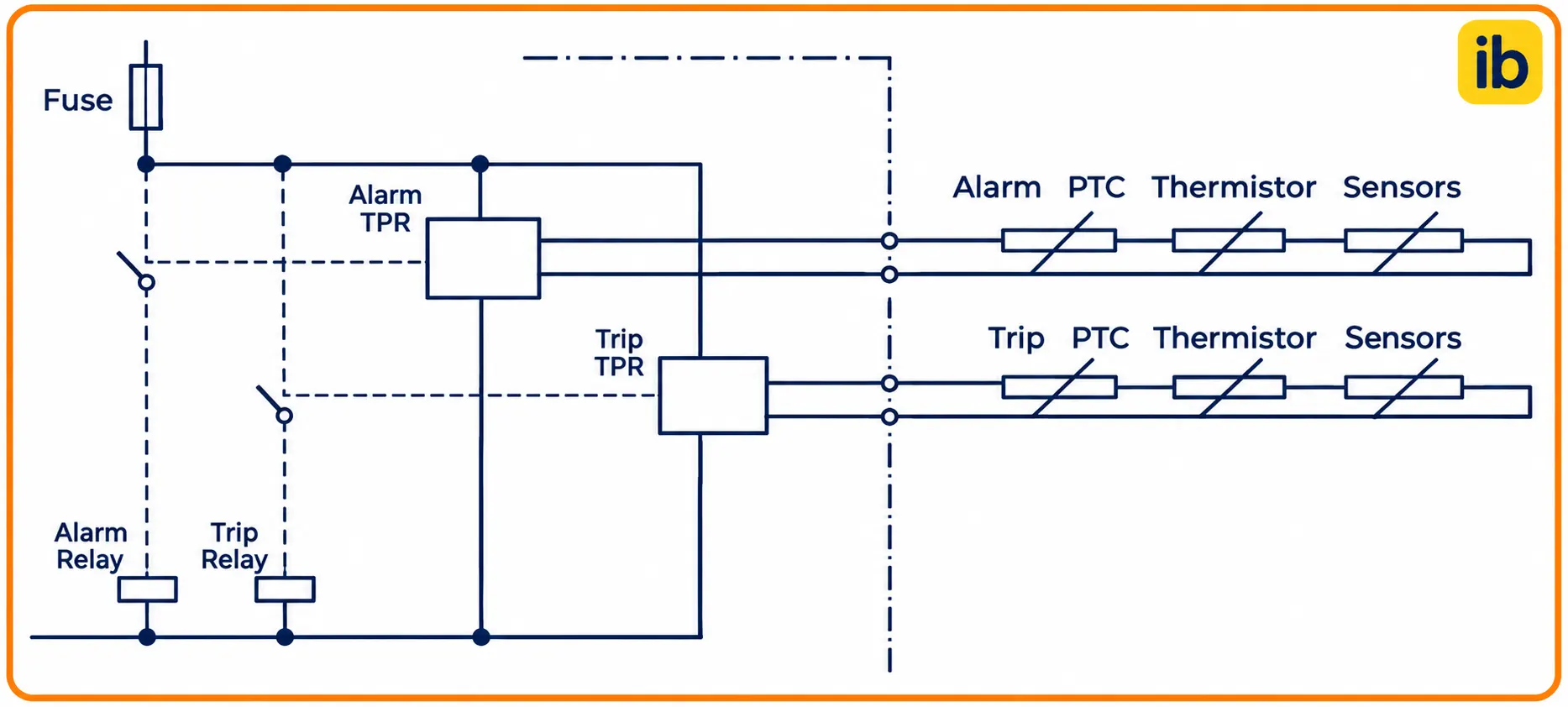
The diagram shows the usual arrangement, with the sensors from all three phases wired in series to two relay terminals and the output contact placed in the contactor coil circuit. When any one sensor gets hot, the loop resistance jumps and the relay opens its contact.
How PTC Sensors Behave Around the Trip Point
Single PTC sensors for motors follow DIN 44081, and triple sensors, three in one moulded set for a 3 phase winding, follow DIN 44082. The standard defines the resistance at fixed points around the nominal response temperature, often written as TNF.
| Temperature Point | Single Sensor, DIN 44081 | Triple Sensor, DIN 44082 |
|---|---|---|
| TNF minus 20 K | 250 Ω or less | 750 Ω or less |
| TNF minus 5 K | 550 Ω or less | 1650 Ω or less |
| TNF plus 5 K | 1330 Ω or more | 3990 Ω or more |
| TNF plus 15 K | 4000 Ω or more | 12000 Ω or more |
Within about 10 K the resistance of a triple set climbs from below 1650 Ω to above 3990 Ω. A relay that trips near 3 to 4 kΩ and resets near 1.5 to 2 kΩ therefore acts almost exactly at the rated sensor temperature.
A PTC motor sensor is not a measuring element like an RTD, it behaves like a temperature switch. You can tell that a winding passed its limit, but not by how many degrees.
Motor Thermistor Protection Relay Trip and Reset Values
Electrical Engineering Portal gives typical IEC control unit values of 3300 Ω plus or minus 100 Ω for trip and 1650 Ω plus or minus 100 Ω for reset, with short circuit detection at 15 Ω or less. Control units of this kind are covered by IEC 60947 8, while IEC 60034 11 deals with built in thermal protection of the motor.
The ABB CM MSE data sheet lists a trip band of 2.7 to 3.7 kΩ and a reset band of 1.7 to 2.3 kΩ. It also limits the total resistance of the series sensors to 1.5 kΩ in the cold state.
Relays with short circuit detection also trip if the sensor leads are shorted, which would otherwise hide a hot winding forever. Most units latch after a trip and need a manual reset, similar to other protective relays, so an operator must investigate before restarting.
Always choose a relay with short circuit and open circuit monitoring for motors in critical service. A pinched sensor cable that shorts during maintenance is far more common than most engineers expect.
Choosing the Sensor Response Temperature
In motor thermistor protection, the nominal response temperature is matched to the insulation class of the winding, explained in motor insulation classes. Electrical Engineering Portal lists trip sensors at 130 °C for Class B, 150 °C for Class F and 175 °C for Class H motors.
Sensors at the class limit, wired to the trip relay.
Sensors 5 to 10 °C lower for early warning.
Separate PTC or RTD in the bearing housings.
Large motors often carry two sensor sets, an alarm group 5 or 10 °C below the trip group, as the same source explains. The alarm gives the control room time to reduce load before the trip group stops the drive.
Wiring Motor Thermistor Protection
The ABB data sheet allows sensor cable runs of up to 2 × 400 m at 2.5 mm² and 2 × 100 m at 0.75 mm². Keep the sensor cable apart from power cores, and use shielded twisted pair cable near drives, since induced voltage can cause nuisance trips.
In a motor control centre, the thermistor relay normally sits in the starter module next to the overload relay. Its auxiliary contact is also wired back to the PLC or DCS so the trip reason is clear.
Loop Resistance Formula
Before commissioning, check that the cold resistance of the whole loop stays below the limit of the relay. The loop includes every sensor in series plus the go and return resistance of the cable.
ρ for copper = 0.0178 Ω mm² per m
Example: 3 sensors at 250 Ω worst case cold value
Cable L = 100 m, A = 1.5 mm²
Cable part = 2 × 100 × 0.0178 ÷ 1.5 = 2.37 Ω
R loop = 750 + 2.37 = 752.37 Ω, below 1500 Ω
Thermistor Loop Resistance Calculator
Second Worked Example: Six Sensors on One Relay
Electrical Engineering Portal notes that up to six sensors may be connected in series if the total resistance at ambient stays at or below 1.5 kΩ. Using the worst case DIN figure of 250 Ω each gives 6 × 250 = 1500 Ω before adding any cable, which leaves no margin.
In practice a new sensor at 25 °C reads far below its worst case value, often around 100 Ω or less, which gives about 600 Ω for six sensors. Measure the real cold value and enter it in the calculator, and use two relays if the loop is still close to the limit.
Thermistor Inputs on VFDs
Most modern drives accept a PTC loop directly on an analog or dedicated input and can be set to warn or trip, as part of VFD parameter configuration. This makes motor thermistor protection very useful, because a self cooled motor running at low speed loses fan airflow while current stays near normal.
Drive output voltage pulses can couple noise into sensor leads, and the sensor circuit must be safely isolated from the windings. Check the drive manual for its insulation requirements, and see VFD overload trip causes for other heat related trips.
When a drive input is used, test the trip by heating one sensor or by inserting a resistor of about 4 kΩ in the loop. Never assume the parameter is active just because the wiring is in place.
Motor Thermistor Protection vs Overload Relay
- Measures actual winding temperature.
- Detects blocked cooling, high ambient and dirty fins.
- Protects at low speed on a VFD.
- Handles frequent starts and heavy duty cycles.
- Simple, robust relay with fail safe logic.
- Slow for locked rotor on rotor critical motors.
- Cannot be added easily to an existing motor.
- Gives a trip only, not a temperature value.
- Sensor failure inside the winding needs a rewind to fix.
The best practice is to use both, an overload relay or motor protection relay for fast current faults and motor thermistor protection for slow overheating. On large motors, RTDs in the windings give an actual temperature trend instead, as explained in how an RTD works.
6 Vital Checks for Testing Motor Thermistor Protection
- Measure loop resistance cold with a low voltage multimeter.
- Confirm the reading is below 1.5 kΩ and above the short circuit level.
- Check insulation of the loop to earth at low voltage only.
- Simulate a trip with a resistor of about 4 kΩ.
- Short the loop and confirm short circuit detection operates.
- Verify the reset and the trip signal to PLC or DCS.
Record the cold loop resistance at commissioning, since a later change shows sensor or cable damage. Never connect an insulation tester across the sensor pair, and disconnect the relay before testing the windings.
The sensors used for motor thermistor protection are placed in the winding overhang during manufacture or rewinding. They cannot be added to a finished winding, so specify them when ordering the motor.
Troubleshooting Common Problems
Repeated nuisance trips of motor thermistor protection with a cold motor usually point to induced voltage or a loose terminal, while a trip with a genuinely hot motor points to cooling, load or supply problems. Check fan cowl blockage, dust on fins, voltage unbalance and the number of starts per hour.
A loop reading of several kilohms on a cold motor means an open sensor or a broken lead inside the winding. Plan a rewind and meanwhile protect the motor with careful overload settings based on the motor full load current.
ABB Thermistor Relay Data Sheet
SIRIUS Thermistor Relay Video
Motor Thermistor Protection FAQ
It is a scheme in which PTC sensors inside the stator windings are monitored by a dedicated relay. The relay trips the motor when the winding reaches its rated temperature.
Because it measures real winding heat, it catches problems that current based relays miss. Blocked cooling, high ambient and slow running on a drive are typical examples.
Typical IEC control units trip near 3300 ohms and reset near 1650 ohms. The ABB CM MSE data sheet lists a trip band of 2.7 to 3.7 kilohms.
Many relays also trip below about 15 ohms to detect a shorted loop. Always check the exact trip, reset and short circuit values in the data sheet of your own relay model.
Up to six sensors are commonly allowed, provided the total cold resistance stays within the limit of the relay. That limit is usually 1.5 kilohms for the whole loop.
Measure the actual cold resistance and add the cable resistance before deciding. If the remaining margin is small, split the sensors between two separate relays instead.
DIN 44081 covers single PTC sensors for motor protection. DIN 44082 covers triple sensors, three sensors moulded in series for the three phases of a winding.
Both define resistance at fixed points around the nominal response temperature, such as 5 K and 15 K above it. A triple set has three times the single sensor values at each of these points.
Yes, most modern drives have an input that accepts a PTC loop and can be set to warn or trip. It must be enabled correctly in the drive parameters.
Check the insulation level that the drive manual requires for the sensor circuit. Then test the function by inserting a resistor of about 4 kilohms in the loop.
PTC sensors are rated for only a few volts, and a 500 or 1000 volt test can destroy them. A damaged sensor is buried in the winding and is very hard to replace.
Use a low voltage multimeter on the sensor loop instead. Disconnect the relay and short the sensor leads to earth before testing winding insulation.
Yes, because thermistors respond slowly to a locked rotor or a sudden short overload. Some large motors also have a rotor that overheats long before the stator sensors notice.
Use the overload relay for fast current faults and the thermistor relay for slow heating. Together with motor thermistor protection, they give complete thermal cover for every operating condition of the motor.
Related Articles
- Thermal Overload Relay Explained
- NTC and PTC Thermistor Working
- Motor Insulation Classes
- Motor Protection Relay Types
- VFD Parameter Configuration
External References
- Thermistor Motor Protection Relays CM MSE, ABB
- Practical Tips for Thermistor Motor Protection, Electrical Engineering Portal
- Thermistor, Wikipedia
What We Learn Today
- Motor thermistor protection uses PTC sensors in the windings whose resistance rises sharply near the rated temperature, so a simple relay can trip the motor.
- Typical relays trip near 3300 Ω, reset near 1650 Ω and detect shorts below 15 Ω, with a cold loop limit of 1.5 kΩ.
- Use thermistors together with an overload relay, since thermistors catch slow overheating while current relays handle locked rotor and fast faults.