
Every backup generator, power plant, and vehicle charging system relies on the same alternator working principle, a rotating magnetic field inducing voltage in a set of stationary windings.
The alternator working principle relies on electromagnetic induction, a rotating magnetic field from the rotor sweeps past stationary stator windings, inducing an alternating voltage exactly as Faraday's law of induction predicts.
This machine shares much of its construction with the synchronous motor, run in reverse to generate power instead of consuming it.
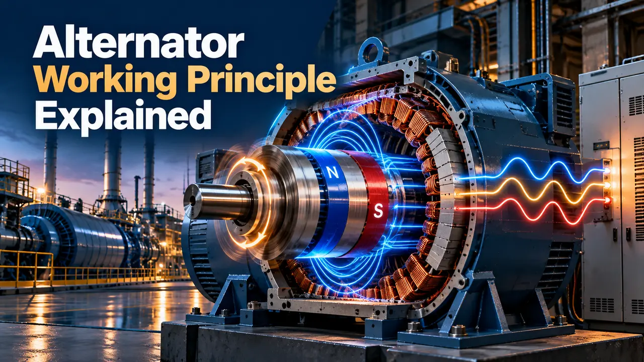
The Core Alternator Working Principle
A rotor, carrying a magnetic field created by a DC current through its field winding, is spun by a prime mover such as a diesel engine, steam turbine, or water turbine.
As that rotating magnetic field sweeps past the stationary stator windings, it induces an alternating voltage in each winding, following Faraday's law that a changing magnetic flux through a conductor induces an electromotive force.
Three separate stator windings, spaced 120 electrical degrees apart, each see the rotating field at a slightly different moment, producing the three phase output most industrial machines deliver.
The Role of the Prime Mover
The prime mover, whether a diesel engine, gas turbine, steam turbine, or water turbine, supplies the mechanical energy that keeps the rotor spinning against the opposing torque created once electrical load is applied.
As load increases, the electrical output draws more mechanical power from the shaft, and the prime mover's governor must respond by increasing fuel or steam flow to hold speed steady.
Why the Field Rotates Instead of the Output Winding
Placing the heavy, high current output windings on the stationary stator avoids the need for large slip rings and brushes to carry that current off a spinning shaft.
Only the much smaller DC field current needs to reach the rotating rotor, which can be done through modest slip rings or, in many modern designs, through a brushless exciter system entirely.
Main Components
| Component | Function | Location |
|---|---|---|
| Field winding | Creates the rotating magnetic field | Rotor |
| Armature winding | Where output voltage is induced | Stator |
| Slip rings or brushless exciter | Delivers DC current to the field winding | Rotor shaft |
| Automatic voltage regulator | Maintains stable output voltage | External control cabinet |
Common Applications by Machine Size
Small portable and standby units apply the same alternator working principle at a scale of a few kilowatts, often using a simple brush type exciter and a basic voltage regulator for cost reasons.
Utility scale power plant machines apply the identical alternator working principle at hundreds of megawatts, with far more sophisticated cooling, protection, and automatic voltage regulation systems supporting the much larger electrical and mechanical stresses involved.
Vehicle charging systems use a small, high speed version of the same design, though most convert the output to DC internally with built in rectifier diodes before it ever reaches the battery.
Frequency and Speed Relationship
Output frequency depends directly on rotor speed and the number of magnetic poles built into the machine, following the relationship that frequency equals poles times speed in revolutions per minute, divided by 120.
A two pole machine must spin at 3000 revolutions per minute to produce 50 hertz output, while a four pole machine reaches the same frequency at only 1500 revolutions per minute.
Salient Pole vs Cylindrical Rotor Designs
A salient pole rotor has distinct protruding poles, well suited to slower speed machines like hydroelectric generators where a large number of poles is needed to reach standard grid frequency.
A cylindrical rotor is smooth and mechanically stronger at high speed, making it the preferred choice for fast spinning turbine driven machines in gas and steam power plants.
Why Speed Must Stay Constant
Since frequency is locked to rotor speed, a prime mover's governor must hold speed within a tight band, any drift directly shows up as a frequency error on the output.
This is different from an induction generator, which can tolerate more speed variation since it depends on slip relative to the grid rather than a fixed rotor speed.
Voltage Regulation Under Load
Alternator vs DC Generator
Alternator
Simpler brush arrangement, higher achievable output, standard for nearly all modern power generation.
DC Generator
Needs a commutator and heavy brushes on the output side, largely obsolete for bulk power.
Understanding the alternator working principle explains why this design displaced the older DC generator almost entirely for stationary and vehicle power generation over the past century.
Paralleling Multiple Machines
Running two or more machines on the same bus requires matching voltage, frequency, and phase sequence closely before closing the connecting breaker, otherwise a severe circulating current can result.
Once synchronized, governor droop settings determine how load shares between the paralleled machines as total demand changes, preventing one unit from taking on a disproportionate share of the load.
Modern synchronizing relays automate much of this process, monitoring the voltage difference across the open breaker and only permitting closure once conditions fall within a safe matching window.
Testing and Commissioning
An insulation resistance test on the stator windings before first startup catches moisture or contamination that could otherwise lead to an early winding failure once the machine is energized.
A no load speed and voltage check confirms the governor and voltage regulator are both functioning correctly before the machine is ever connected to an actual load.
Load bank testing, applying a controlled resistive load in steps, verifies the machine can sustain its full rated output and that voltage regulation remains stable throughout the range.
Common Mistakes to Avoid
Maintenance and Common Failure Points
Bearing wear is one of the most common failure modes, since the rotor spins continuously for the machine's entire operating life, making vibration monitoring and periodic lubrication essential preventive tasks.
Insulation breakdown in the stator windings, often accelerated by heat, moisture, or contamination, is checked periodically with insulation resistance testing and, on larger machines, with more detailed partial discharge monitoring.
Slip ring wear on brush type exciter systems requires periodic brush replacement and ring cleaning, one of the reasons many modern machines have moved to brushless exciter designs instead.
Watch: Three Phase AC Generator Animation
Alternator Working Principle FAQs
Related Articles on This Site
- Synchronous Motor Working Principle
- How to Calculate Generator Size for Industrial Load
- AC Motors and Generators, Back EMF
- Current Transformer Working Principle
- Motor Efficiency Classes, IEC 60034
External References
- Working Principle of an Alternator, Electrical4U
- AC Generator Construction and Working, ElectricalEasy
What We Learn Today
- A rotating magnetic field from the rotor induces alternating voltage in the stationary stator windings.
- Output frequency is fixed by rotor speed and pole count, requiring tight governor control.
- An automatic voltage regulator holds output voltage steady as connected load changes.