
Knowing the kVAR formula is one thing. Actually specifying the right capacitor bank for a real facility, standard size, fixed or automatic, and where to install it, is a different skill entirely. This capacitor bank sizing guide covers that second half.
A correctly calculated kVAR figure is only the starting point. Rounding to a real capacitor size, choosing fixed versus automatic, and deciding where in the plant it goes are the decisions that actually determine whether capacitor bank sizing earns back its cost.
If you already know the power triangle and the basic kVAR formula, this guide picks up right where that ends and moves into full capacitor bank sizing. It is built for engineers, facility managers, and energy consultants sizing a real capacitor bank for an industrial or commercial site.
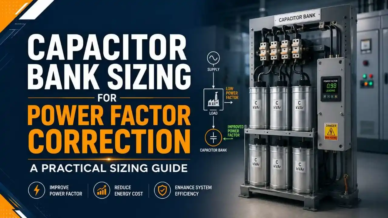
This guide covers the step by step capacitor bank sizing process, how to pick a standard capacitor size, when to choose fixed versus automatic banks, where to physically install the bank, harmonic considerations, and the sizing mistakes that quietly waste the most money.
Why Proper Capacitor Bank Sizing Matters
Oversizing wastes capital and risks pushing the system into a leading power factor. Undersizing leaves utility penalties in place. Getting the capacitor bank sizing right the first time protects both the budget and the equipment.
Correct sizing also improves voltage regulation, reduces line losses, and frees up capacity elsewhere in the system, while incorrect sizing risks voltage rise, harmonic resonance, or capacitors that simply do not do the job they were bought for.
The Capacitor Sizing Formula
- kW is the real load in kilowatts
- θ1 is the phase angle of the current power factor
- θ2 is the phase angle of the target power factor
This formula is the foundation of every capacitor bank sizing calculation, whether solved by hand or through a calculator. Using power factor values directly instead of angles, the same formula reads as kVAR equals kW times the square root of one over PF1 squared minus one, minus the square root of one over PF2 squared minus one. Either version gives the same answer.
Worked example: A 500 kW load sitting at 0.80 power factor, targeting 0.95, needs kVAR equal to 500 times the difference between 0.750 and 0.329, which comes to 210.5 kVAR, a textbook capacitor bank sizing result.
Peak demand, not average load, is what utilities calculate penalties against. Capacitor bank sizing against a monthly average routinely leaves a facility undercorrected at the exact moment the penalty clock is running.
Step by Step Capacitor Bank Sizing Process
Measure the current power factor
Use a power quality meter at the main service entrance, review utility bill kW and kVA values, or take portable readings at key motor feeders, capturing data across different operating conditions. This first step drives every later capacitor bank sizing decision.
Set the target power factor
Most engineers target 0.95, since it clears typical utility penalty thresholds of 0.85 to 0.90, leaves margin for load swings, and avoids the overcorrection risk that comes with chasing a perfect 1.0.
Calculate the required kVAR
Apply the formula using the peak demand load, not the average, since penalties are calculated against peak, not average, consumption.
Select a standard capacitor size
Capacitor bank sizing relies on fixed standard sizes such as 25, 50, 75, 100, 150, 200, 250, 300, 400, and 500 kVAR. Round up to the next standard size above the calculated figure.
Verify the resulting power factor
Recalculate the power factor after adding the selected capacitor size to confirm capacitor bank sizing landed at or above target without tipping into an over corrected, leading condition.

Watch: Capacitor Bank Sizing Explained
This video walks through the same kVAR sizing method with additional worked examples.
Video: "Capacitor Bank Sizing (KVAR) for Power Factor Improvement", via YouTube.
Fixed vs Automatic Capacitor Banks
Once capacitor bank sizing gives a target kVAR figure, the next decision is whether that capacity should be fixed or switched in steps.
Fixed Capacitor Banks
Constant kVAR output with no switching. Capacitor bank sizing for this type works best on stable loads with minimal variation, such as a single large motor or a small facility running near constant load.
Automatic Capacitor Banks
Multiple steps switch in and out as a controller tracks power factor in real time. Best for facilities with more than 20% load variation across shifts or seasons.
Capacitor Installation Location Strategies
Capacitor bank sizing determines how much correction is needed, but where that correction physically sits also changes the outcome.
| Strategy | Best For |
|---|---|
| Centralized, at main service | Small to medium facilities under 1000 kW with concentrated loads |
| Distributed, at load centers | Large facilities over 1000 kW with loads spread across the site, since it also reduces feeder losses |
| Load specific, at individual motors | Sites with a small number of large motors over 50 HP, correcting right at the source |
Real World Sizing Example
The Scenario
A food processing facility runs between 500 and 800 kW depending on shift, averaging 0.82 power factor, with a target of 0.95. This is a textbook case for walking through capacitor bank sizing end to end.
The Calculation
At the average load of 650 kW, the formula gives roughly 240 kVAR. But checked against the 800 kW peak instead, the requirement rises to about 295 kVAR.
Why Peak Matters Here
Capacitor bank sizing against the average would have left the facility undercorrected during exactly the peak hours when utility penalties are calculated.
The Result
A 300 kVAR automatic bank, built from six 50 kVAR steps, installed at the main service, correcting the facility across its full load range rather than just at one operating point.
Harmonic Considerations in Sizing
Harmonics add a layer capacitor bank sizing cannot ignore. Standard capacitors work fine where total harmonic distortion stays under 5% and loads are mostly linear, motors, heaters, and lighting. Once THD climbs past that threshold, or VFDs and other electronic loads make up a large share of the facility, a standard bank risks resonance at the fifth or seventh harmonic.
Detuned capacitor banks, which pair a series reactor with the capacitor to shift the tuned frequency away from common harmonics, cost roughly 20 to 30% more but avoid the premature failures that standard capacitors suffer in harmonic rich systems.
Common Sizing Errors
✔ Do
- Size against peak demand, using the highest recorded 15 minute demand, since this is the single most important rule in capacitor bank sizing
- Use full three phase formulas, including the square root of 3 factor, for three phase measurements
- Build in margin for planned load growth, typically 10 to 20%
- Measure harmonic content before specifying standard versus detuned capacitors
✘ Don't
- Base capacitor bank sizing on average load instead of peak demand
- Install a fixed bank on a load with more than 20% variation
- Default to centralized installation for a large, distributed facility without evaluating feeder losses
- Ignore harmonics until capacitors start failing prematurely
FAQs on Capacitor Bank Sizing
You May Also Like
Power Factor Correction Explained: kVAR Formula and Capacitor Sizing
Before sizing a bank, it helps to have the fundamentals solid. This guide covers the power triangle, why a low power factor costs a facility money, and the basic kVAR formula with a live calculator to try the numbers yourself.
Read Full Article →What we learn today
- Capacitor bank sizing starts with the kVAR formula, but the real skill is measuring peak demand accurately and rounding to a standard size correctly.
- Fixed banks suit stable loads, while automatic banks earn their higher cost back on any load with more than 20% variation.
- Installation location, centralized, distributed, or load specific, changes both the cost and the effectiveness of the correction.
- Harmonic distortion above 5% calls for detuned capacitors, since standard units risk resonance and early failure in harmonic rich systems.
- Sizing against average load instead of peak demand is the single most common and most expensive mistake in capacitor bank sizing projects.