
A power cut should never wipe out a running total, a recipe setpoint or the step a machine had reached. Retentive storage decides which values survive the outage and which ones start again from zero when the controller restarts.
Some PLC values must survive a power failure while others must reset for safety. PLC retentive memory, set up with care, keeps counters, totals and setpoints alive without bringing back dangerous commands.

What Is PLC Retentive Memory?
PLC retentive memory is the part of controller data memory whose values are kept when power is removed or the CPU goes from STOP to RUN, so a counter, totaliser or setpoint resumes from its last value. Every other tag is non retentive and returns to zero or its start value, as described in PLC memory addressing.
A batch counter that resets after a short outage, or a motor command that comes back on by itself, both point to a wrong PLC retentive memory setting inside the PLC block diagram memory area.
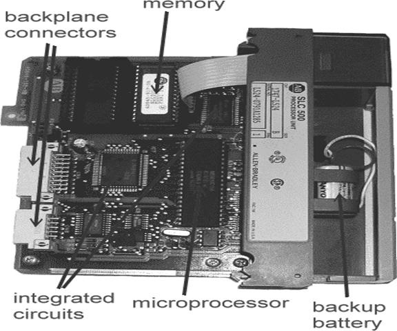
Automation Primer explains that the program and data both live in RAM, which may be volatile or non volatile. Older platforms kept that RAM alive with a battery or super capacitor, while newer ones copy the program to an SD or CompactFlash card and reload it at power up.
Retentive vs Non Retentive Data
Retentive data holds values that must not be lost, such as production counts, running hours, recipe parameters and the active step of a sequence. Non retentive data holds live working values, such as one shots from ONS, OSR and OSF instructions, temporary math results and output commands that must restart in a safe state.
| Item | Typical Setting | Reason |
|---|---|---|
| Production and batch counters | Retentive | Shift totals must survive an outage |
| Running hours and totalisers | Retentive | Maintenance and billing data |
| Recipe setpoints from HMI | Retentive | Operator should not re enter values |
| Sequence step number | Retentive with care | Resume only after operator confirms |
| Motor and valve commands | Non retentive | Must restart in a safe off state |
| Alarm latches and one shots | Non retentive | Fresh evaluation after power up |
| Temporary math results | Non retentive | Recalculated every scan |
According to Automation Primer, Siemens marker memory can be set retentive or not and defaults to 16 retentive bytes, while Omron keeps holding relays and the DM area but clears the CIO and Work areas. Allen Bradley memory is described there as all retentive.
How Each Platform Handles Retain
Tick Retain per tag in an optimised data block, or per block in a standard block, and set retentive marker ranges.
All controller tags keep their values, but instructions such as OTE and TON reset during prescan.
Declare VAR RETAIN for power loss and VAR PERSISTENT to survive a program download.
Set retentive ranges for V memory, timers, counters and latch relays in the CPU parameters.
In TIA Portal, an optimised block lets you tick Retain for individual tags, while a standard block is retentive as a whole. The available retain bytes are fixed by the CPU, so the PLC data types you choose decide how far that budget stretches.
On Rockwell controllers, every tag value stays in memory, so the important point is the prescan. During the first scan after power up, OTE outputs and TON timers are cleared, while OTL latches, counters and the RTO accumulator keep their values, as covered in PLC timer instructions TON, TOF and RTO.
In CODESYS style controllers, a VAR RETAIN value survives a power cycle and a warm reset, but a cold reset clears it. VAR PERSISTENT goes one step further and survives a fresh download, which suits calibration constants and lifetime counters.
On every new project, write down a retain list before you start coding and review it with the process engineer. It is far easier than hunting for missing Retain ticks after the first plant shutdown.
Battery, Super Capacitor and Flash Backup
Retained values must be stored somewhere while power is off. Older CPUs keep the RAM alive with a lithium battery or a super capacitor, and many newer CPUs copy retentive data into internal flash at power down using energy stored in the power supply.
The AutomationDirect DL205 user manual gives clear numbers for its CPUs. The super capacitor holds data for 4.5 days minimum on the D2 230 and D2 240, but only about 15 hours on the D2 260 and about 1.5 hours on the D2 262.
The same manual states that the capacitor on the higher models is not meant to retain memory and mainly gives time to swap the battery. A healthy cell is therefore part of PLC retentive memory design, and causes of battery failure explains why heat inside panels shortens battery life.
Siemens S7 1200 and S7 1500 CPUs, and Rockwell controllers with an energy storage module, save PLC retentive memory data to non volatile memory instead of relying on a battery. Even so, keep the panel UPS healthy, because brown outs can still corrupt values that are being written.
Automation Primer notes that on older platforms a dead battery meant the whole program was lost, not just the data. That is why many Indian plants still keep printed program backups for very old controllers.
Warm, Cold and Hot Restart
A warm restart keeps retentive data and resets everything else to its start value. A cold restart, available on older S7 300 and S7 400 CPUs, resets retentive data too, and a hot restart on S7 400 continues the program from the point of interruption, as you can trace in how the PLC scan cycle works.
Newer S7 1200 and S7 1500 CPUs support only the warm restart type, so correct Retain ticks matter even more. A memory reset or a download that reinitialises a changed data block clears PLC retentive memory as well.
7 Smart Rules for PLC Retentive Memory
The first scan routine is the safety net. Use the first scan bit from PLC diagnostic status bits to put a retained sequence on hold until an operator confirms that the machine is in the expected position.
Test the design during the factory acceptance test by switching off the panel supply in the middle of a batch. Record every counter, setpoint and step value before and after, and compare them with the retain list.
Retain Byte Budget Formula
Each CPU has a fixed PLC retentive memory size, shown in its datasheet. To estimate the need, multiply each data type count by its size and add the Boolean bits divided by eight, rounded up.
Usage percent = Retain bytes ÷ Available bytes × 100
Example:
150 REAL, 100 DINT, 200 INT, 160 BOOL, available 10240 bytes
4 × 150 = 600, 4 × 100 = 400, 2 × 200 = 400, 160 ÷ 8 = 20
Total = 600 + 400 + 400 + 20 = 1420 bytes
Usage = 1420 ÷ 10240 × 100 = 13.9 percent
The available figure of 10240 bytes is only an example, so always use the real value for your CPU and firmware. Padding inside structures can add a few bytes, so keep at least 30 percent spare for future changes.
PLC Retentive Memory Calculator
Second Worked Example: Packaging Line Retain Plan
A packaging line in Pune needs 40 REAL recipe values, 24 DINT shift counters, 60 INT step numbers and 96 Boolean mode flags to survive a power cut. The estimate is 160 + 96 + 120 + 12 = 388 bytes.
With a small CPU offering 2048 retain bytes, that is about 19 percent, leaving room for growth. Group these values in one data block so the data move instructions that copy recipes from the HMI write into a single retained area.
Keep retained data in a few clearly named blocks, such as DB_Retain_Recipe and DB_Retain_Counters. Engineers who join the project later can see the PLC retentive memory plan at a glance.
Advantages and Limitations of Retentive Storage
- Counters and totals survive power cuts.
- Operators need not re enter recipes.
- Sequences can resume after a short outage.
- Running hours support maintenance planning.
- Retain bytes are limited by the CPU.
- Retained commands can create restart hazards.
- Batteries and capacitors age and fail.
- Memory reset or reinitialising downloads clear values.
For critical totals, also send values to SCADA or a historian, so a copy of PLC retentive memory data exists outside the controller. Hot standby systems in PLC redundancy keep data aligned between two CPUs.
Troubleshooting PLC Retentive Memory Loss
- Confirm the Retain tick on the exact tag or data block.
- Check that the block was not reinitialised by the last download.
- Read the battery low or storage module status bit.
- Look for a memory reset entry in the diagnostic buffer.
- Verify retentive ranges in the CPU parameters.
- Check first scan logic that may overwrite retained values.
- Confirm the power supply hold up time during outages.
A very common cause is first scan code that copies default values over retained ones. Another is a battery alarm ignored for months, which you can spot in PLC fault handling logs and diagnostic buffers.
Field Applications in Indian Plants
Counters for these jobs come from CTU and CTD instructions, and their accumulators must be inside retentive storage to survive frequent grid dips in industrial estates.
AutomationDirect DL205 PLC Memory Appendix
Retentive Timer Video Lesson
PLC Retentive Memory FAQ
It is the data area whose values survive a power failure or a stop to run change. Counters, totals and setpoints stored there continue from their last value.
Values outside this area return to zero or their start value at power up. This lets the program restart outputs and commands in a known, safe state.
Keep production counters, running hours, totalisers, recipe setpoints and calibration constants in retained storage. These are records of what has already happened in the plant.
Start commands, valve open requests and alarm latches should normally reset to off when power returns. The operator then decides when the equipment runs again after the plant supply comes back.
A warm restart keeps retained values and resets all other data to its start value. A cold restart, found on older S7 300 and S7 400 CPUs, also resets retained data.
Newer S7 1200 and S7 1500 controllers support only the warm restart type. A memory reset from the switch or software still clears retained values completely.
Logix controllers keep all tag values, so there is no Retain tick to set for each tag. The prescan on power up still clears OTE outputs and TON timers.
Latches, counters and the RTO accumulator keep their values through that prescan. Your logic must therefore expect a cleared output and a retained count at the same time.
The AutomationDirect DL205 manual gives at least 4.5 days for the D2 230 and D2 240 models. It gives only about 15 hours for the D2 260 and about 1.5 hours for the D2 262 model.
The manual says the capacitor on higher models is not meant to retain memory for long periods. A fitted and healthy battery is recommended whenever retained data matters.
The usual causes are a missing Retain tick, a reinitialising download or a memory reset. A dead battery or first scan code that writes default values can also do it.
Check the diagnostic buffer and the battery status bit first. Then search the program for any instruction that writes to the counter during the first scan.
Multiply REAL and DINT counts by four bytes and INT counts by two bytes. Add the Boolean count divided by eight and round the result up.
Compare the total with the retain size given in the CPU datasheet for your firmware. Keep about 30 percent spare so later changes do not run out of space.
Related Articles
- PLC Memory Addressing
- PLC Timer Instructions TON, TOF and RTO
- PLC Counter Instructions CTU and CTD
- How the PLC Scan Cycle Works
- PLC Diagnostic Status Bits
External References
- DL205 User Manual Appendix E, PLC Memory, AutomationDirect
- PLC Memory, Automation Primer
- Non volatile Memory, Wikipedia
What We Learn Today
- PLC retentive memory keeps counters, totals and setpoints through a power cut, while non retentive tags reset so commands restart in a safe state.
- Siemens uses Retain ticks, Rockwell keeps all tags but clears OTE and TON in prescan, and CODESYS uses VAR RETAIN and VAR PERSISTENT.
- Budget retain bytes from data type sizes, protect batteries or flash backup, and test a real power cut during the factory acceptance test.
