
Edge detection turns a long input signal into a single scan pulse, so counters, sequences and commands fire exactly once.
A PLC one shot turns a rising or falling edge of an input into a pulse that lasts exactly one scan. It stops counters from racing, commands from repeating and sequences from skipping steps.
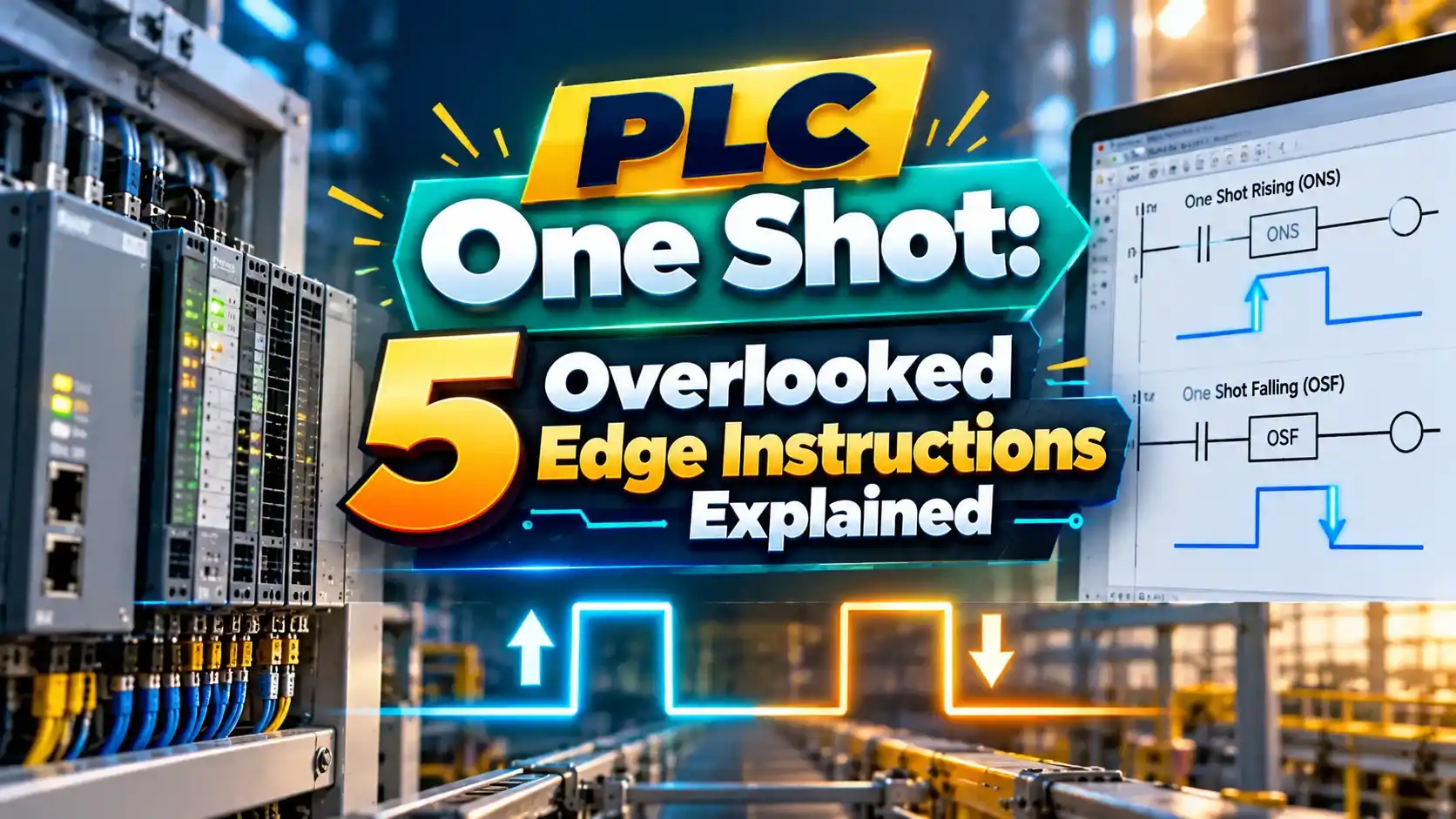
What Is a PLC One Shot?
A PLC one shot is an instruction that makes its output true for only one program scan when its input changes state. It is the software version of a pulse generator and a key idea covered in ladder logic for beginners.
Without edge detection, an input that stays on for half a second is seen as true in every scan during that time. At a 10 ms scan, that is about 50 scans, and any logic tied to that input runs 50 times.

The one shot remembers the previous state of the input in a storage bit. By comparing the old state with the new one, it knows exactly when an edge happens.
This makes it essential for counter instructions, sequence steps, recipe loads and any command that must execute once per button press.
5 Edge Instructions Across Platforms
Inline rising edge instruction that passes rung power for one scan.
One Shot Rising output instruction with separate storage and output bits.
One Shot Falling output that pulses when the input turns off.
IEC 61131 3 function block that detects a rising edge.
IEC 61131 3 function block that detects a falling edge.
Siemens uses positive and negative edge contacts, marked P and N, which need a memory bit just like OSR. The idea is identical even though the symbol looks different.
Choose ONS for quick inline logic and OSR or OSF when you want a named output bit that other rungs can use.
4 Steps Inside a One Shot Scan
This sequence depends completely on the PLC scan cycle. The pulse is always exactly one scan wide, whatever the scan time is.
Because the pulse is so short, you cannot see it with online monitoring most of the time. Use a counter or a latch driven by the pulse when you need to confirm it fired.
Counting Error Formula Without Edge Detection
Counts with edge = 1 per press
Worked example:
Push button held for 500 ms
Scan time = 10 ms
Counts without edge = 500 ÷ 10 = 50
Counts with edge = 1
Error without a one shot = 49 extra counts
This is the classic bug in a new programmer’s batch counter or step sequencer. One press jumps the sequence many steps forward or counts a whole batch in a moment.
Counter instructions in many PLCs already react only to the rising edge of their rung. Still, any add or move logic that runs every scan needs a PLC one shot in front of it.
ONS vs OSR vs OSF Comparison
| Feature | ONS | OSR | OSF |
|---|---|---|---|
| Edge detected | Rising | Rising | Falling |
| Instruction type | Input style, inline | Output style | Output style |
| Storage bit | One bit | Storage bit | Storage bit |
| Output bit | Rung passes | Separate bit | Separate bit |
| Reuse of pulse | Same rung only | Anywhere in program | Anywhere in program |
Each instance must have its own storage bit. Sharing one storage bit between two one shots is a common error that makes one of them stop working, much like reusing addresses covered in PLC memory addressing.
In Studio 5000, ONS uses one BOOL tag, while OSR and OSF each need a storage bit and an output bit. Build a naming rule such as Pump1_Start_OS so bits never overlap.
Where Edge Detection Is Used
Toggle logic is a neat example of a flip flop built in software, similar to the circuits in flip flop types. Each press flips the state because the PLC one shot delivers a single clean pulse.
Shift logic also benefits from edges, as shown in our guide to bit shift and rotate instructions.
Extra Counts Calculator
Longer presses and faster scans make the problem worse. Modern controllers with 1 ms scans can count hundreds of times during a single press.
- Clean single scan pulse from any input.
- Prevents runaway counters and sequences.
- Works the same on every scan time.
- Available on every PLC platform.
- Sharing one storage bit between instructions.
- Placing the one shot inside a skipped routine.
- Using a one shot where a level signal is needed.
- Forgetting the pulse is invisible when monitoring.
Logix General Instructions Manual PDF
OSR and OSF Tutorial Video
PLC One Shot Questions
Related Articles
- PLC Counter Instructions
- How PLC Scan Cycle Works
- PLC Bit Shift and Rotate Instructions
- PLC Timer Instructions
- Latches in Digital Logic
External References
- Understanding PLC Program Commands, One Shots, Control.com
- OSF One Shot Falling Instruction, SolisPLC
- Logix5000 General Instructions, Rockwell Automation
- Signal Edge, Wikipedia
What We Learn Today
- Edge instructions turn a changing input into a pulse that lasts one scan.
- ONS, OSR and OSF are Allen Bradley versions, while R_TRIG and F_TRIG are IEC blocks.
- Every edge instruction needs its own storage bit to work correctly.