
Every tag, every flag, every analog value in a PLC lives somewhere in memory, and that memory is organized in layers, not one flat list.
Ok, let me explain it properly. Bits stack into bytes, bytes stack into words, and words stack into double words. Understanding that nesting is what makes addressing schemes like MW0 or N7:0 actually make sense.
PLC memory addressing organizes data into a nested structure of bits, bytes, words, and double words, where a bit is the smallest single on/off value, eight bits form a byte, two bytes form a 16-bit word, and two words form a 32-bit double word, and understanding this hierarchy is essential for reading addresses correctly and avoiding data overlap mistakes.
PLC Memory Addressing Explained: The Building Blocks
PLC memory addressing starts with the smallest possible unit of information a controller can store, a single bit, and builds upward from there.
Have you got it so far? Good, because every other addressing concept in this guide is really just a variation on that one idea, grouping bits together in consistent, predictable sizes so a program can reference exactly the data it needs.
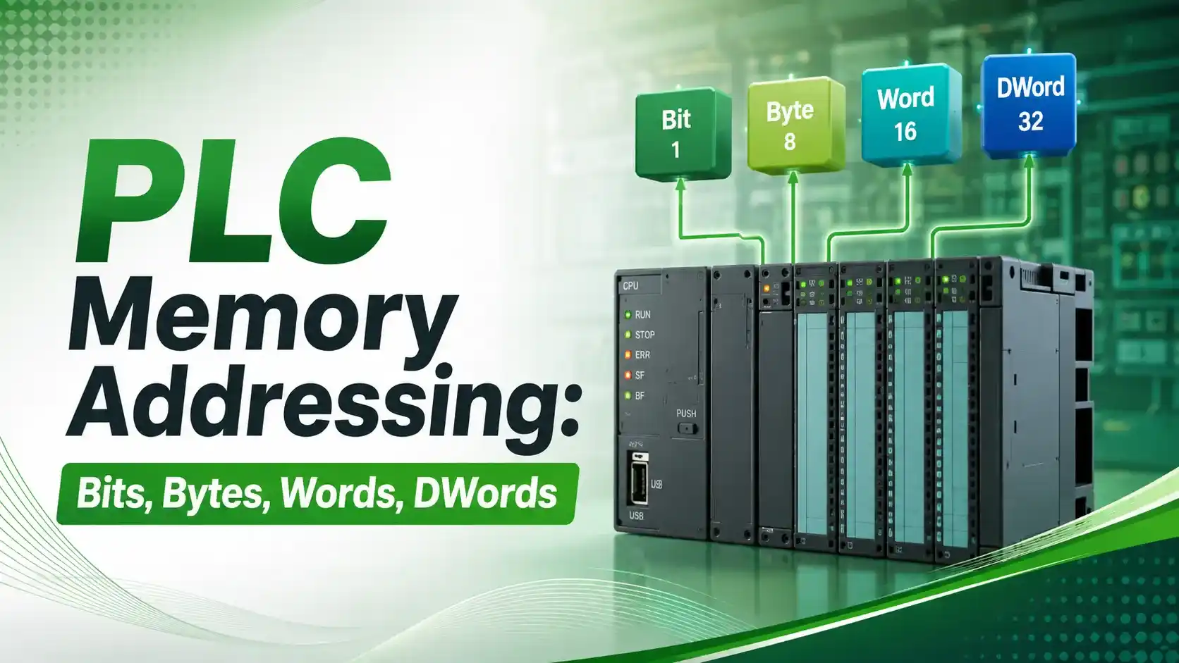
Different PLC platforms expose this structure differently. Siemens uses explicit byte-based addressing like M0.0 or MW0, as shown in this explanation of Siemens even memory addressing. Allen-Bradley's legacy PLC-5 and SLC 500 use file-based addressing like N7:0.
Modern tag-based platforms like ControlLogix hide most of this behind symbolic names, but the underlying memory is still organized the same way. This connects closely to the broader picture covered in our guide to PLC data types.
Bit, Byte, Word, and Double Word Compared
| Unit | Size | Typical Use | Example Address |
|---|---|---|---|
| Bit | 1 bit | Single I/O point, boolean flag, alarm status | M0.0, B3:0/0 |
| Byte | 8 bits | Character data, small counts, byte-oriented status blocks | MB0 |
| Word | 16 bits (2 bytes) | Analog values, integers, most common register size | MW0, N7:0 |
| Double Word | 32 bits (4 bytes, 2 words) | Floating point values, extended-range integers, high-resolution analog | MD0 |
Visualizing the Nested Structure
Four bytes, thirty two bits, one double word. Every layer is just a different way of grouping the exact same underlying bits.
Six Concepts Worth Understanding Properly
1Bit-Level Addressing
Used for anything that's naturally on or off, a single digital input, an internal flag, or one bit inside a status word.
2Byte Grouping
Eight bits form a byte, the base unit in byte-addressable systems like Siemens, where MB0 refers to the whole first byte.
3Word as the Standard Register
Most analog values and integers are stored in 16-bit words, which is why word addressing is the most common size you'll work with.
4Double Words for Extended Data
Floating point numbers and high-resolution or wide-range integers need 32 bits, so they're stored across two consecutive words.
5Memory Overlap
In byte-addressable systems, a word and the bytes that make it up occupy the exact same physical memory, viewed two different ways.
6Byte Order (Endianness)
The order bytes combine into a word or double word varies by platform, and getting it wrong produces a scrambled, nonsensical value.
The Memory Overlap Gotcha
This is genuinely one of the most common sources of subtle PLC bugs, so it's worth walking through carefully.
On a Siemens-style byte-addressable system, MW0 isn't separate memory from MB0 and MB1. It's the same sixteen bits, addressed as one word instead of two bytes.
If one part of a program writes to MB1 directly while another part reads MW0 expecting a stable 16-bit value, the two can interfere with each other in ways that are genuinely difficult to trace.
According to control.com's textbook chapter on memory maps and I/O addressing, this exact overlap behavior is why disciplined address planning matters more in byte-addressable systems than in tag-based ones.
Double words follow the same pattern one level up. MD0 overlaps MW0 and MW2, which overlap MB0 through MB3. Four different addresses, one physical block of memory.
Try It: Address Conversion Calculator
Given a word number and a bit position within that word, this calculator finds the absolute bit number, the byte it falls in, and the double word that contains it.
Let Us Take an Example
A technician needs to find exactly where Word 3, Bit 5 physically sits in memory, down to the byte and double word level.
Word = 3
Bit = 5
Step 1: Absolute bit number
Absolute Bit = Word × 16 + Bit
Absolute Bit = 3 × 16 + 5
Absolute Bit = 48 + 5
Absolute Bit = 53
Step 2: Byte number
Byte = floor(53 ÷ 8)
Byte = 6
Step 3: Bit within that byte
Bit in Byte = 53 mod 8
Bit in Byte = 5
Step 4: Double word number
DWord = floor(3 ÷ 2)
DWord = 1
Have you got it? Good. So Word 3, Bit 5 is the same physical bit as Byte 6, Bit 5, and it lives inside Double Word 1.
Ok, let me explain why this is worth practicing. On platforms that mix addressing styles, being able to convert between word, byte, and bit references quickly saves a lot of confusion when cross-referencing a program against a wiring diagram or an HMI tag list.
Byte Order and Why It Trips Up Integrations
When two bytes combine into a word, or two words combine into a double word, the order they're combined in matters.
Big-endian systems store the most significant byte first. Little-endian systems store the least significant byte first. Get this wrong when integrating two different platforms, and a value like 1000 can silently become a completely different number.
This is a frequent, and frequently overlooked, source of bad values during PLC-to-PLC or SCADA communication integration, and it's worth checking explicitly rather than assuming both systems agree.
A Step-by-Step Approach to Reliable Addressing
Learn the platform's native addressing style
Confirm whether the system uses byte-addressable, file-based, or tag-based addressing before writing any logic.
Plan the memory map before coding
Reserve word and double word ranges deliberately, rather than letting addresses get assigned ad hoc as the program grows.
Watch for overlap on byte-addressable systems
Avoid mixing byte-level and word-level access to the same memory region without a clear, documented reason.
Confirm byte order on any integration
Check big-endian versus little-endian behavior explicitly whenever two different platforms exchange word or double word data.
Document address usage as the program grows
Keep a running reference of what each memory region holds, so future changes don't accidentally collide with existing data.
Verify with a known test value
Write a recognizable test pattern and confirm it reads back correctly across every addressing style used in the system.
Good Practices for PLC Memory Addressing
✓ Do
- Plan and document memory allocation before a program grows large enough to make mistakes costly
- Understand your platform's specific overlap behavior between bytes, words, and double words
- Verify byte order explicitly on any cross-platform data exchange
- Use word-level access consistently once a region is designated for word data
✗ Don't
- Mix byte-level and word-level writes to the same memory region without documentation
- Assume byte order matches automatically between two different PLC platforms
- Let memory addresses get assigned ad hoc without any planned structure
- Ignore address overlap as a possible cause of an intermittent, hard-to-reproduce data bug
Worth Reading if You Want to Go Deeper
Questions Students and Technicians Often Ask
External References
- Memory Maps and I/O Addressing, control.com Textbook
- Siemens S7 Byte, Word, Double Word Memory Addressing Explained, Industrial Monitor Direct
- Siemens PLC Even Memory Addressing Explained, Industrial Monitor Direct
What we learn today
- PLC memory is organized in a nested hierarchy: bits form bytes, bytes form words, and words form double words.
- A bit is 1 bit, a byte is 8 bits, a word is 16 bits, and a double word is 32 bits, each larger unit built from the ones below it.
- On byte-addressable platforms like Siemens, word and double word addresses overlap the underlying byte addresses, which is a common source of subtle data bugs.
- A worked example converted Word 3, Bit 5 into Byte 6, Bit 5, confirming it lives inside Double Word 1.
- Byte order, big-endian versus little-endian, must be verified explicitly on any cross-platform data integration to avoid scrambled values.