
An inductor and a capacitor can swap energy back and forth so smoothly that the pair rings at one natural frequency. Learn how that frequency is set, how sharp the peak is and where tuned circuits earn their place in real products.
Put an inductor and a capacitor together and they favour one frequency above all others. LC resonance is the reason radios tune, oscillators ring and filters pick one signal out of many.
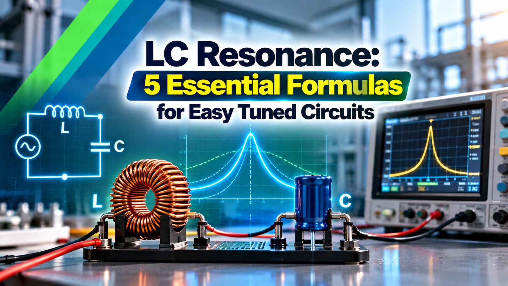
What Is LC Resonance?
LC resonance is the condition in a circuit containing an inductor L and a capacitor C where the inductive reactance exactly equals the capacitive reactance, so the two cancel and energy swings between them at one natural frequency. It builds directly on the ideas of reactance and impedance, so revise those first if the terms feel new.
An inductor stores energy in its magnetic field, while a capacitor stores it in its electric field. When one empties, the other fills, and the exchange repeats like a pendulum swinging between two heights.
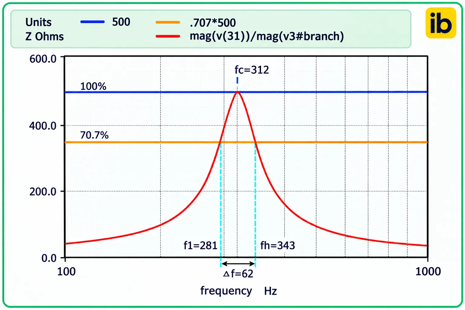
The graph above shows how the impedance of a parallel tank peaks sharply at one frequency and falls away on either side. The width of that peak, measured at 70.7 percent of the maximum, is the bandwidth we calculate later.
How Energy Swings During LC Resonance
In an ideal loop with no resistance the swinging would continue for ever at the frequency of LC resonance. Real coils have copper resistance, real capacitors have dielectric loss, and every cycle loses a little energy, so the oscillation decays unless something tops it up.
An amplifier that feeds back just enough energy each cycle turns this ringing into a steady sine wave. That is the heart of the Colpitts and Hartley circuits described in types of transistor oscillators.
At LC resonance the current circulating inside a parallel tank can be Q times larger than the current drawn from the source. A tank with a Q of 100 fed with 1 mA can carry about 100 mA between its own L and C.
5 Essential LC Resonance Formulas
| Formula | Expression | What It Tells You |
|---|---|---|
| Reactance balance | XL = XC, so 2πfL = 1 ÷ (2πfC) | Condition that defines resonance |
| Resonant frequency | f0 = 1 ÷ (2π√(LC)) | The natural frequency of the pair |
| Quality factor | Q = (1 ÷ R) × √(L ÷ C) | Sharpness of the peak for series R |
| Bandwidth | BW = f0 ÷ Q | Width between the 70.7 percent points |
| Dynamic resistance | RD = L ÷ (C × R) | Peak impedance of a parallel tank |
The LC resonance frequency formula comes straight from setting XL equal to XC and solving for f. Notice that f0 depends on the product LC, so doubling L and halving C leaves the frequency unchanged but changes the impedance level and Q.
Q = (1 ÷ R) × √(L ÷ C)
BW = f0 ÷ Q
Example:
L = 100 µH, C = 100 pF, series R = 10 Ω
√(L × C) = √(100 µH × 100 pF) = 0.1 µs
f0 = 1 ÷ (2π × 0.1 µs) = 1591.55 kHz
√(L ÷ C) = √(1,000,000) = 1000 Ω
Q = 1000 ÷ 10 = 100.0
BW = 1591.55 ÷ 100 = 15.92 kHz
Here the term √(L ÷ C) is called the characteristic impedance of the tank, and it equals the reactance of L or C at resonance. The worked example gives 1000 Ω, and dividing it by the 10 Ω of loss resistance gives the Q directly.
Always convert µH and pF into henry and farad before using the formula, since most wrong answers come from mixed units. A quick sanity check is that 100 µH with 100 pF sits near 1.6 MHz, in the medium wave radio band.
Resonant Frequency and Q Calculator
Series vs Parallel LC Resonance
L and C in series with the source; impedance falls to just R at resonance.
L and C across each other; impedance rises to a high peak at resonance.
Two tuned circuits linked by mutual inductance or a small capacitor.
ROHM TechWeb explains that in a series RLC circuit the impedance is at its minimum, equal to R, at resonance, so the current is at its maximum. In a parallel RLC circuit the reverse happens, with impedance at its maximum and line current at its minimum.
This is why a series circuit is called an acceptor, since it passes its resonant frequency easily, and a parallel tank is called a rejector, since it blocks that frequency in a series path. Both types rely on the same LC resonance condition, only the way they are connected changes the result.
Q Factor and Bandwidth in Practice
All About Circuits defines Q as X ÷ R, where X is the reactance of L or C at resonance and R is the series resistance, and gives the bandwidth as fc ÷ Q. Their worked series example resonates at 323 Hz with a Q of 5 and a bandwidth of 64 Hz between 291 Hz and 355 Hz.
The band edges are the half power points, where the response has fallen to 0.707 of its peak, which is 3 dB down as explained in decibels in electronics. A high Q means a narrow, selective LC resonance peak, while a low Q gives a broad, gentle response.
In a series circuit at resonance, the voltage across L or across C is Q times the source voltage. A 1 V signal driving a series circuit with Q of 100 can therefore put about 100 V across a small capacitor, so voltage rating matters even in low power designs.
Coil Q usually limits the whole circuit, because copper loss rises with frequency due to the skin effect in conductors. Capacitor loss matters too, and the equivalent series resistance of a capacitor adds straight into R in the Q formula.
The name Q simply stands for quality factor, a figure of merit for coils introduced by K S Johnson of Western Electric in 1914. It is also equal to 2π times the energy stored divided by the energy lost per cycle.
Second Worked Example: Tuning a Radio Stage
Suppose a medium wave receiver must tune to 1000 kHz and the coil has an inductance of 250 µH. Rearranging the formula gives C = 1 ÷ ((2πf)² × L) with f = 1 MHz and L = 250 µH, which is about 101.3 pF.
If the same tank has 20 Ω of loss, √(L ÷ C) is about 1571 Ω and Q is about 79, so the bandwidth is roughly 12.7 kHz. That is close to the 9 kHz channel spacing used for AM broadcast in India, and a varactor diode can replace the variable capacitor for electronic tuning.
Step by Step Tank Circuit Design
Remember that stray capacitance of wiring, PCB traces and the transistor input adds to C, often by 5 to 20 pF at radio frequencies. Include it in the calculation, or the measured LC resonance will land lower than the design value.
Use C0G or NP0 ceramic or silver mica capacitors in tuned circuits, because their capacitance barely moves with temperature. X7R and Y5V types drift and shift the resonant frequency as the board warms up.
Where LC Resonance Is Used
In an inductive proximity sensor, a metal target near the coil absorbs energy through eddy currents, the tank Q collapses and the oscillator amplitude drops. The sensor electronics watch that amplitude and switch the output.
For very stable frequencies, a quartz crystal replaces the LC tank because its equivalent Q runs into tens of thousands, as covered in crystal oscillator working principle. A cheaper middle ground is described in ceramic resonators.
In power systems, LC resonance is often a problem rather than a feature. Capacitor banks can resonate with the supply transformer inductance at a harmonic frequency, which is why designers use detuned reactors, as discussed in capacitor bank sizing for power factor correction.
- Selects one frequency with simple passive parts.
- High Q gives sharp selectivity and low noise.
- Parallel tank provides high impedance for gain.
- Easy to tune with a variable C or a varactor.
- Coils are bulky at low frequencies.
- Component tolerance and temperature shift f0.
- Stray capacitance lowers the actual frequency.
- Unwanted resonance can cause overvoltage and ringing.
Troubleshooting a Tuned Circuit
- Measure L and C separately with an LCR meter at the working frequency.
- Add an estimate of stray and transistor capacitance to C.
- Sweep the circuit with a signal generator and scope to find the real peak.
- Check the capacitor voltage rating against Q times the drive voltage.
- Look for a lossy coil core or wrong ferrite grade if Q is low.
- Retest after warm up to see temperature drift.
An oscilloscope with a swept source quickly shows whether the peak is at the right place and how wide it is. The basics of using one are covered in the cathode ray oscilloscope, and the same method works with a modern digital scope.
Series and Parallel Tank Lecture Notes
LC Resonant Circuit Tutorial Video
LC Resonance FAQ
It is the condition where the reactance of an inductor equals the reactance of a capacitor in the same circuit. The two cancel and energy swings between the magnetic and electric fields at one frequency.
That frequency is called the resonant frequency f0. It depends only on the values of L and C, following f0 = 1 ÷ (2π√(LC)) for a low loss circuit.
Convert L into henry and C into farad, multiply them and take the square root. Then divide one by 2π times that square root to get f0 in hertz.
For example, 100 µH with 100 pF gives about 1591.55 kHz. Doubling either L or C lowers the frequency by a factor of about 1.414, not by half.
A series circuit has minimum impedance at resonance, so it passes maximum current at that frequency. This is why engineers often call it an acceptor circuit.
A parallel tank has maximum impedance at resonance, so it draws minimum line current. Engineers call it a rejector, and it is widely used in oscillators and tuned amplifiers for LC resonance.
Q describes how sharp and selective the resonant peak is. It equals the reactance at LC resonance divided by the total loss resistance present in the circuit.
A high Q gives a narrow bandwidth and strong selectivity. A low Q gives a broad response that passes a much wider range of frequencies with less peak gain.
Bandwidth equals the resonant frequency divided by the quality factor of the circuit. It is measured between the two half power points where the response is 0.707 of the peak.
A tank at 1591.55 kHz with a Q of 100 has a bandwidth of about 15.92 kHz. Raising Q to 200 would halve that bandwidth to about 7.96 kHz.
Stray capacitance from wiring, PCB traces and active devices adds to the design value of capacitance. Component tolerance, often 5 or 10 percent, also shifts the result.
Measure the real parts at the working frequency and include strays in the sum. A small trimmer capacitor then lets you set the exact LC resonance frequency on the bench.
It sets the frequency of oscillators in inductive proximity sensors, radio links and wireless chargers. It also forms the band pass and trap filters used in many communication and power circuits.
Unwanted LC resonance matters too, for example between capacitor banks and transformer inductance. Detuned reactors are fitted to stop harmonic currents from being amplified.
Related Articles
- What Is Reactance
- Inductor Working Principle
- Crystal Oscillator Working Principle
- Types of Transistor Oscillators
- Impedance and Reactance in AC Circuits
External References
- Series and Parallel Resonant Tank Circuits, Stanford University EE133
- Q and Bandwidth of a Resonant Circuit, All About Circuits
- LC Circuit, Wikipedia
What We Learn Today
- LC resonance happens when inductive and capacitive reactance are equal, giving a natural frequency f0 = 1 ÷ (2π√(LC)) set only by L and C.
- A series circuit shows minimum impedance at resonance while a parallel tank shows maximum impedance, which suits acceptor filters and oscillator tanks respectively.
- Q equals reactance divided by loss resistance and bandwidth equals f0 ÷ Q, so 100 µH, 100 pF and 10 Ω give Q of 100.