
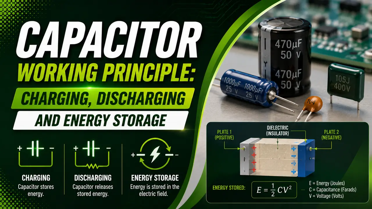
A capacitor stores electrical energy in an electric field between two conducting plates separated by a dielectric.
It charges and discharges exponentially, at a rate determined entirely by τ = RC -- the time constant.
This guide covers the physical working principle, the RC time constant, the charging and discharging equations, energy storage, and key applications -- with an interactive RC calculator.
When voltage is first applied to an uncharged capacitor, current flows at its maximum value. As the capacitor charges, the current falls and the voltage rises -- both following exponential curves -- until the capacitor reaches supply voltage and current drops to zero.
How a Capacitor Works
Two parallel metal plates face each other with an insulating dielectric between them.
When connected to a DC supply, electrons accumulate on the negative plate and leave the positive plate. This charge separation creates an electric field across the dielectric -- energy is stored in that field, not in the plates themselves.
The capacitor cannot sustain current indefinitely -- as charge builds up, the plate voltage opposes further charging.
Current falls as plate voltage approaches supply voltage. At full charge, current is zero. A fully charged capacitor behaves as an open circuit to DC.
In AC circuits, the capacitor continuously charges and discharges as the voltage alternates. It passes AC but blocks DC. The capacitance fundamentals guide covers the plate geometry and dielectric constant in detail.
Charging and Discharging Equations
Vs = supply voltage (V)
τ = RC time constant = R × C (seconds)
e = Euler's number ≈ 2.718
Current during charging: I(t) = (Vs / R) × e−t/τ -- starts at maximum, falls to zero
τ = RC time constant for the discharge path
Current during discharge: I(t) = −(V₀ / R) × e−t/τ -- negative because current reverses
Both voltage and current decay exponentially to zero
RC Time Constant: Voltage at Each Time Step
The table below shows what percentage of the supply voltage the capacitor reaches at each time constant. These values are the same for every RC circuit regardless of the actual values of R and C -- only the absolute time scale changes.
Energy Stored and Capacitive Reactance
C = capacitance (farads)
V = voltage across the capacitor (V)
Example: 470 µF at 400V stores: E = 0.5 × 470×10⁻⁶ × 400² = 37.6 joules
This is why large electrolytic capacitors in power supplies must be discharged before service.
f = frequency (Hz)
C = capacitance (farads)
Xc falls as frequency rises -- a capacitor passes high frequency signals and blocks low frequency ones.
Example: 100 nF at 50 Hz: Xc = 31,831 Ω. At 10,000 Hz: Xc = 159 Ω.
RC Time Constant and Charging Calculator
Where Capacitors Are Used: 6 Key Applications
Power Supply Filtering
Large electrolytic capacitors smooth the ripple voltage after a rectifier. They charge on voltage peaks and discharge between peaks, keeping the output voltage stable. See capacitor bank sizing for the reactive power version of this concept.
Signal Coupling and Decoupling
A series capacitor passes the AC component of a signal while blocking DC bias. A shunt capacitor bypasses high frequency noise to ground while leaving the DC supply undisturbed. See the decoupling capacitor guide.
RC Timing Circuits
The predictable τ = RC time constant makes capacitors the basis of timing in oscillators, monostable circuits, and PWM generators. Changing R or C changes the timing without redesigning the circuit.
Power Factor Correction
Capacitor banks supply reactive power locally to inductive loads, reducing apparent power demand. See the full capacitor bank sizing guide for the kVAR calculation method.
Sensor Signal Conditioning
Capacitors in signal conditioning circuits filter noise from sensor outputs. A low pass RC filter passes slow process signals and attenuates high frequency electrical interference from cables and motor drives.
Energy Storage and Flash
Large capacitor banks store energy for pulsed applications -- camera flash units, defibrillators, and laser pulse generators. They charge slowly through a high value resistor and discharge rapidly through a low resistance path. The formula E = ½CV² governs the stored energy.
Capacitor Types and Where to Use Each
| Type | Typical Range | Key Characteristics | Best Use |
|---|---|---|---|
| Electrolytic (aluminium) | 1 µF to 100,000 µF | Polarised, high capacitance, high ESR. Fails if reverse biased or voltage exceeded. | Power supply filtering, bulk decoupling |
| Ceramic (MLCC) | 1 pF to 100 µF | Non polarised, very low ESR, tiny SMD sizes. Capacitance varies with voltage and temperature. | High frequency decoupling, bypass caps on PCBs |
| Tantalum | 0.1 µF to 1000 µF | Polarised, very stable, low leakage, can fail explosively if reverse biased or overcurrent. | Precision timing, portable devices |
| Film (polyester, polypropylene) | 1 nF to 100 µF | Non polarised, excellent stability, low loss, low temperature coefficient. | Audio circuits, RF filters, motor capacitors |
| Supercapacitor (EDLC) | 1 F to thousands of F | Very high capacitance, low voltage (2.7V max per cell), very high cycle life. | Energy harvesting, UPS bridging, backup power |
For a detailed comparison of all capacitor types and construction materials, see the capacitor types guide and the PCB design rules for placement and derating guidelines.
Watch: Capacitors Explained -- Charging, Discharging and RC Time Constant
Capacitor Working Principle Questions
External References
- RC Charging Circuit and Time Constant -- Electronics Tutorials
- Discharging a Capacitor: Formula and Graphs -- Electrical4U
What We Learn Today
- Charging: V(t) = Vs × (1 − e^(−t/τ)) -- voltage rises exponentially, current falls
- Discharging: V(t) = V₀ × e^(−t/τ) -- both voltage and current decay exponentially
- Time constant τ = RC -- at 1τ the capacitor reaches 63.2%; at 5τ it is practically fully charged
- Energy stored: E = ½CV² -- doubles with voltage, so voltage rating matters critically
- Capacitive reactance Xc = 1/(2πfC) -- falls as frequency rises; capacitors pass AC, block DC
- A fully charged capacitor is an open circuit to DC -- current only flows during the charging transient