
Nearly every digital clock signal on earth starts inside a tiny sliver of quartz. Here is exactly how a crystal oscillator turns electricity into a precise mechanical vibration, with a real Pierce oscillator circuit and a frequency drift simulator you can try right now.
What Is a Crystal Oscillator?
A crystal oscillator is a circuit that uses a vibrating sliver of quartz to generate an extremely stable clock signal. The quartz itself, not the surrounding electronics, decides the exact frequency.
Every microcontroller, digital clock, and radio transceiver needs a dependable heartbeat to synchronize its internal operations. That heartbeat comes from a crystal oscillator, working alongside components like the flip-flops it clocks and the digital logic covered in our encoder vs decoder guide.
This guide covers the five essential facts behind crystal oscillator frequency stability, from the physical effect that makes quartz vibrate to the real circuit almost every digital IC uses to drive it.
How the Piezoelectric Effect Creates Oscillation
The entire crystal oscillator depends on one physical property of quartz, discovered long before electronics existed.
Voltage Applied to the Quartz
An AC voltage from the driving circuit is applied across metal electrodes on the crystal's surfaces.
The Crystal Physically Deforms
The inverse piezoelectric effect causes the quartz to flex slightly in response to that voltage.
Mechanical Vibration Feeds Back
As the crystal springs back, it generates its own voltage, which the circuit amplifies and feeds back in.
Oscillation Locks to Resonance
This loop settles into a stable, self-sustaining vibration at the crystal's precise resonant frequency.
5 Essential Facts About Crystal Oscillator Frequency Stability
These five facts explain why quartz became the default choice for precision timing, and what actually limits its accuracy in the real world.
The Piezoelectric Effect Powers Everything
Quartz converts electrical energy into mechanical vibration and back again. Apply voltage and it flexes, flex it and it generates voltage, a two-way relationship that makes self-sustaining oscillation possible.
The Crystal's Cut Sets the Frequency, Not the Circuit
The physical dimensions and cut angle of the quartz wafer determine its resonant frequency. The surrounding circuit only sustains the vibration, it does not choose the frequency.
Every Crystal Has Two Closely Spaced Resonances
A real crystal resonates at both a series frequency and a slightly higher parallel frequency. Which one an oscillator circuit uses depends on how it is designed.
Frequency Stability Is Excellent, But Not Perfect
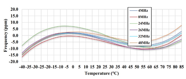
Quartz crystals easily reach parts-per-million stability, but temperature, aging, and mismatched load capacitance can all still shift the actual output frequency.
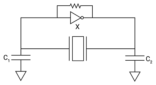
The Pierce Oscillator Drives Nearly Every Digital Clock
One inverter, two capacitors, a feedback resistor, and the crystal itself, this simple configuration is the standard circuit behind almost every digital IC clock source in use today.
Frequency Stability Compared Across Oscillator Types
Crystal oscillator frequency stability looks impressive on its own, but it becomes clearer when placed next to other common timing sources.
The Crystal's Equivalent Circuit
Electrically, a vibrating crystal behaves like a tuned circuit built from its own mechanical properties, commonly called the Butterworth-Van Dyke model.
Inductance L1
Capacitance C1
Resistance R1
What is happening: L1, C1, and R1 represent the crystal's mass, mechanical stiffness, and internal friction as it vibrates. C0 is simply the physical capacitance between the two metal electrodes sandwiching the quartz.
A real example: At series resonance, the motional inductance and capacitance cancel out, leaving only R1 as the impedance. At the slightly higher parallel resonance, C0 comes into play, shifting the effective frequency upward.
Why it works: Most oscillator circuits, including the Pierce configuration, deliberately operate the crystal near its parallel resonance, since the added load capacitors from the circuit itself interact predictably with C0 to fine-tune the exact output frequency.
Load Capacitance and Frequency Pulling
The exact frequency a crystal produces in a real circuit depends on more than the crystal alone.
Load capacitance: CL = (C1 × C2) / (C1 + C2) + Cs
Worked example: C1 = 18pF, C2 = 18pF, stray capacitance Cs = 4pF
CL = (18 × 18) / (18 + 18) + 4 = 9 + 4 = 13pF
If the actual load capacitance in the finished circuit does not match the value the crystal was manufactured and specified for, the output frequency shifts slightly away from its nominal value, an effect called frequency pulling.
Try It: Frequency Drift Simulator
Pick a nominal frequency, then drag the temperature slider to see how far a standard AT-cut crystal actually drifts.
Crystal and Oscillator Type Comparison
Click each tab to see how different crystal-based solutions trade off cost against stability.
The AT-cut is the most common quartz cut, chosen for its low, predictable frequency drift over a wide temperature range, following the characteristic cubic curve shown in the simulator above.
A temperature-compensated crystal oscillator adds a circuit that measures ambient temperature and applies a correcting voltage, flattening out most of the drift without the power cost of active heating.
An oven-controlled crystal oscillator holds the crystal at a fixed elevated temperature inside a small heated enclosure, eliminating most temperature-driven drift at the cost of higher power consumption and warm-up time.
MEMS oscillators replace quartz with a vibrating silicon structure, trading some frequency stability for smaller size, higher shock resistance, and easier integration onto a single chip.
Oscillator Comparison Table
| Type | Typical Stability | Relative Cost | Best For |
|---|---|---|---|
| Standard Crystal (XO) | ±10 to 50 ppm | Low | General digital clocking |
| TCXO | ±0.5 to 2 ppm | Medium | Cellular, GPS, portable radios |
| OCXO | ±0.001 to 0.01 ppm | High | Network timing, lab references |
| MEMS Oscillator | ±20 to 100 ppm | Low to Medium | Compact, shock-resistant designs |
Applications of Crystal Oscillators
Microcontroller Clocks
Nearly every microcontroller relies on a crystal to time its instruction execution.
Real-Time Clocks and Watches
A 32.768 kHz crystal divides cleanly down to exactly one second per tick.
Radio Transceivers
Crystal references keep transmit and receive frequencies precisely on channel.
GPS Timing
Stable local oscillators help GPS receivers lock onto satellite signals quickly.
Network Synchronization
OCXOs and TCXOs keep telecom and data network timing tightly aligned.
Medical Devices
Precise timing supports accurate sampling in diagnostic and monitoring equipment.
Notice how many of these roles have nothing obviously in common with each other. A wristwatch, a satellite receiver, and a hospital monitor share almost no design similarities, yet all three quietly depend on the same tiny sliver of vibrating quartz to keep their timing honest.
Crystal Aging Over Time
Even at a perfectly stable temperature, a crystal's frequency slowly drifts over the years due to internal stress relief and minor mass changes at the electrodes.
Notice that aging front-loads most of its drift into the first year, then settles into a slower, roughly linear rate afterward, which is why long-term timing systems often specify a break-in period before final calibration.
This is also why some manufacturers sell pre-aged crystals for critical timing applications, deliberately running them for several weeks before shipment so the steepest part of the aging curve happens at the factory rather than in the field.
Advantages and Limitations of Crystal Oscillators
Why Quartz Still Dominates Timing
Limitations to Keep in Mind
Download Crystal Oscillator References
These two official application notes go deeper into oscillator specification and real-world stability behavior.
Clock Oscillators Application Note
Official Microchip reference covering accuracy, stability, and crystal aging
Reference Oscillator Crystal Requirements
Official NXP application note with real frequency vs temperature curves
Watch: Crystal Oscillator Explained
This video covers crystal oscillator construction, working principle, and real-world uses.
FAQs on Crystal Oscillator Frequency Stability
External References
- Microchip, Clock Oscillators Application Note
- NXP, Reference Oscillator Crystal Requirements Application Note
- DigiKey, How to Meet Low-Power Circuit Timing Requirements Using SPXOs
- YouTube, Crystal Oscillator Explained: Construction, Working and Uses
What we learn today
- Crystal oscillators rely on the piezoelectric effect, converting electrical energy into precise mechanical vibration and back again.
- The crystal's physical cut and dimensions, not the circuit, determine its exact resonant frequency.
- The Pierce oscillator, built from an inverter, two capacitors, and a resistor, drives nearly every digital clock crystal in use today.
- Frequency stability, while excellent, still shifts with temperature, aging, and load capacitance mismatch.
- TCXOs and OCXOs exist specifically to compensate for the temperature drift a standard crystal cannot avoid on its own.