
Nearly every low cost microcontroller ticks to the beat of a tiny slab of ceramic, not quartz.
That single material swap changes the accuracy, the startup time, and the price, all at once.
A ceramic resonator is a piezoelectric timing component that vibrates mechanically at a specific frequency when driven electrically, generating the clock signal a microcontroller or digital circuit needs to keep time.
Every digital circuit needs a heartbeat. Something has to define exactly how fast the logic gates step through their cycles.
Quartz crystals have handled that job for decades, and they still do in anything needing real precision. But a huge share of consumer electronics doesn't need that precision, and that's exactly where ceramic resonators took over.
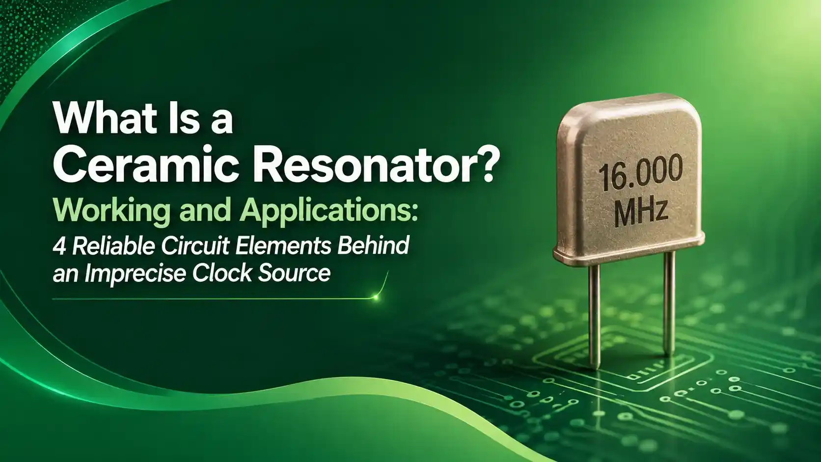
According to ECS Inc's resonator principles reference, a ceramic resonator relies on the same piezoelectric effect as quartz, just built from a synthetic ceramic instead of a natural crystal lattice.
That ceramic, typically lead zirconate titanate, is far easier and cheaper to manufacture than cutting and polishing quartz to precise angles.
The tradeoff shows up immediately in the numbers. Where a quartz crystal might hold frequency to within 10 to 30 parts per million, a ceramic resonator often drifts by 300 to 5,000 ppm instead.
For a huge range of applications, that looser tolerance simply doesn't matter. A microcontroller blinking an LED or scanning a keypad doesn't care if its clock is off by half a percent.
What follows is the real circuit model behind that behavior, the math that predicts its exact oscillation frequency, and where engineers should and shouldn't reach for one.
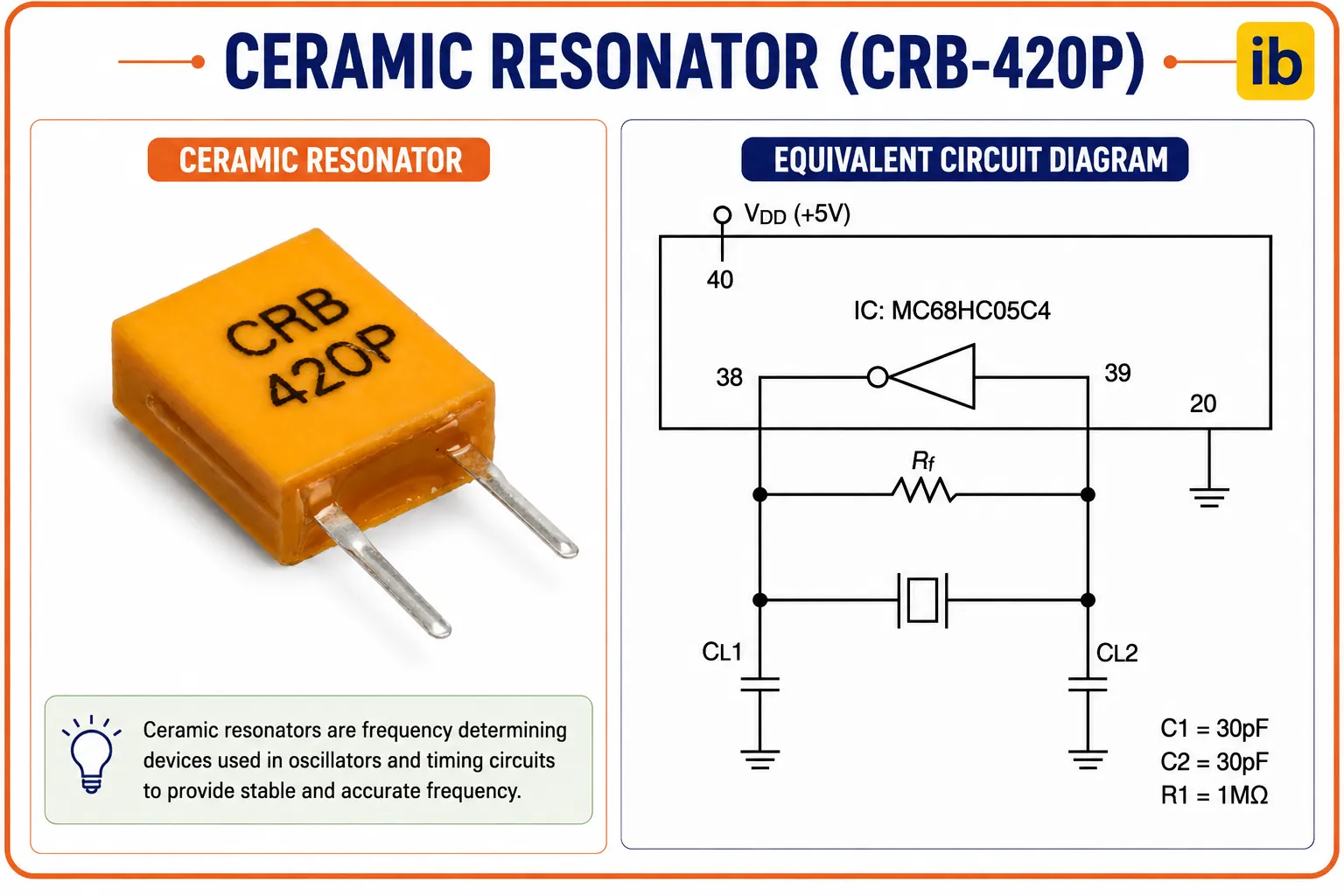
The 4 Elements of the Equivalent Circuit Model
Engineers never model a ceramic resonator as a single part, a point emphasized in Analog Devices' timing component comparison. Near its resonant frequency, it behaves exactly like a small combination of electrical components.
Motional Inductance
Represents the mechanical mass of the vibrating ceramic element, in series with the rest of the motional branch.
Motional Capacitance
Represents the mechanical compliance, or springiness, of the ceramic element as it flexes.
Motional Resistance
Represents internal mechanical losses. Ceramic resonators run higher here than quartz, which is exactly why their Q factor is lower.
Shunt (Static) Capacitance
The ordinary capacitance between the electrodes themselves, sitting in parallel with the entire motional branch.
Interactive Pulled Frequency Formula
Adding load capacitance shifts the actual oscillation frequency above the resonator's raw series resonant frequency. Enter real values to see this pulled frequency calculated live.
Ceramic Resonator vs Quartz Crystal: Real Numbers
The practical differences documented by Zbotic's design comparison come down to a handful of measurable specs.
| Parameter | Ceramic Resonator | Quartz Crystal |
|---|---|---|
| Frequency tolerance | 300 to 5,000 ppm | 10 to 30 ppm |
| Typical startup time | 300 microseconds to 1 ms | 1 to 10 ms |
| Q factor | Lower, broader resonance peak | Higher, narrow and stable |
| External load capacitors | Often built in (3-pin types) | Required externally |
| Relative cost | 30 to 60% cheaper | Higher |
2-Pin vs 3-Pin Ceramic Resonator Packages
Package choice changes how many external components a design actually needs on the board.
2-Pin (Bare Resonator)
Just the ceramic element itself. Requires two external load capacitors wired to ground, same as a quartz crystal circuit.
3-Pin (Integrated Load Caps)
Built-in load capacitors inside the same package, per Murata's CERALOCK product line. Connect directly with no extra parts.
Applications of Ceramic Resonators
Per general ceramic resonator references, these components appear across a wide range of cost sensitive electronics.
Microcontroller Clocks
General purpose timing where absolute accuracy isn't critical.
Remote Controls
Infrared and RF remote transmitter timing references.
Automotive Electronics
Murata's CSTCE_V series serves powertrain and safety modules.
Consumer Electronics
TVs, appliances, and toys needing low cost timing.
USB Peripherals (Low Speed)
Where tolerance requirements are more relaxed.
Household Appliances
Timers and simple digital control panels.
Inside the Oscillator Circuit: Rf and Rd
A resonator alone doesn't oscillate. It needs an inverting amplifier and two supporting resistors to actually sustain oscillation, as detailed in Silicon Labs' oscillator design application note.
If Rf is too large, or if the inverter's input insulation resistance is too low, loop gain collapses and oscillation simply stops. This is a genuine failure mode, not a theoretical one.
Do's and Don'ts of Using a Ceramic Resonator
✓ Do
- Choose a quartz crystal instead for USB, Bluetooth, or CAN bus timing needs
- Match load capacitance to the resonator's specified CL rating exactly
- Use the fast startup advantage for battery powered, frequently sleeping devices
- Check operating temperature range against your application's real environment
✗ Don't
- Use a ceramic resonator for a real-time clock needing tight long-term accuracy
- Assume a 3-pin part's built-in load caps match every circuit's requirements
- Ignore aging drift over the product's expected operating lifetime
- Mix resonator types across a differential clock pair without checking matching specs
Reference Materials on Ceramic Resonators
FAQs on Ceramic Resonators
External References
- Ceramic Resonator, Wikipedia
- Replacing Crystals and Ceramic Resonators with Silicon Oscillators, Analog Devices
- Crystal Oscillator vs Resonator, Circuit Digest
- Ceramic Resonator Principles, ECS Inc
- Oscillator Design Considerations (AN0016.0), Silicon Labs
What we learn today
- A ceramic resonator uses the piezoelectric effect in a synthetic ceramic, typically PZT, to generate a stable oscillating signal.
- Near resonance, it behaves like four circuit elements: motional inductance L1, motional capacitance C1, motional resistance R1, and shunt capacitance C0.
- Adding load capacitance pulls the actual oscillation frequency above the raw series resonant frequency, following F equals Fr times the square root of 1 plus C1 divided by C0 plus CL.
- Ceramic resonators trade accuracy for cost and speed: 300 to 5,000 ppm tolerance versus a crystal's 10 to 30 ppm, but startup in microseconds instead of milliseconds.
- Applications like USB, Bluetooth, and CAN bus timing still require the tighter tolerance only a quartz crystal reliably provides.