
Push too much current through a power inductor and its core runs out of magnetic capacity, so inductance collapses and current shoots up in microseconds. Knowing the saturation rating and checking peak current keeps converters cool, quiet and reliable.
Inductor saturation is one of the most common reasons a switching regulator runs hot or fails. Learn what the Isat rating means, how core materials behave and how to pick an inductor with safe margin.
What Is Inductor Saturation?
Inductor saturation is the condition in which the magnetic core of an inductor cannot store more flux, so further current produces little extra flux and the inductance falls sharply. A saturated part behaves more like a piece of wire than an inductor, and current through it rises much faster than the design expects.
Every magnetic material has a maximum flux density, called Bsat. The flux in the core is set by the number of turns and the current, as Faraday law and Ampere law describe, so the current at which the core approaches Bsat is the saturation current of the inductor.
The curve shows flux density rising almost linearly at first and then levelling off as inductor saturation sets in. The slope of this curve is the permeability, and because inductance depends on permeability, the inductance falls as the curve flattens.
Isat and Irms: Inductor Saturation vs Heating Ratings
Power inductor datasheets list two current ratings, one for inductor saturation and one for heating. Mixing them up is the most common inductor selection mistake made by students and young designers.
The DC current at which inductance has fallen by a stated percentage from its low current value.
The current that causes a stated temperature rise from copper and core heating.
The highest instantaneous current in your circuit, equal to average plus half the ripple.
Coilcraft explains that Irms is a thermal rating derived from the measured temperature rise caused by current flow, while Isat is a performance rating linked to the instantaneous current. Its datasheets show the current at which inductance drops by 10, 20 and 30 percent, because makers do not all use the same drop.
The practical rule is simple: compare peak current with Isat, and compare RMS current with Irms. The RMS value includes the ripple, and the ESR of the output capacitor handles the ripple that the inductor passes on.
An inductor can be thermally safe and still deep in inductor saturation, or well below saturation and still overheating. Isat and Irms come from different physics, so both checks are always needed.
Why Inductor Saturation Happens in the Core
L in henry, Ipk in ampere, N turns, Ae core area in m²
Design rule: Bpk must stay below Bsat at the hottest core temperature
Example, custom gapped ferrite choke:
L = 100 µH, Ipk = 2 A, N = 30, Ae = 0.4 cm² = 0.00004 m²
Bpk = 0.0001 × 2 ÷ (30 × 0.00004)
Bpk = 0.0002 ÷ 0.0012 = 0.167 T
Below about 0.3 T, so a typical power ferrite stays out of saturation
The formula shows the levers you have. More turns raise inductance faster than flux, a bigger core area lowers flux density, and an air gap lowers permeability so that the core needs more current to saturate, while also concentrating stored energy in the gap.
Core losses, covered in eddy current loss and hysteresis loss, depend on the flux swing caused by ripple, not on the DC level. Inductor saturation, in contrast, depends on the peak flux, which is why a large DC bias pushes a part toward the knee even when ripple is small.
Ferrite vs Powdered Iron Core Behaviour
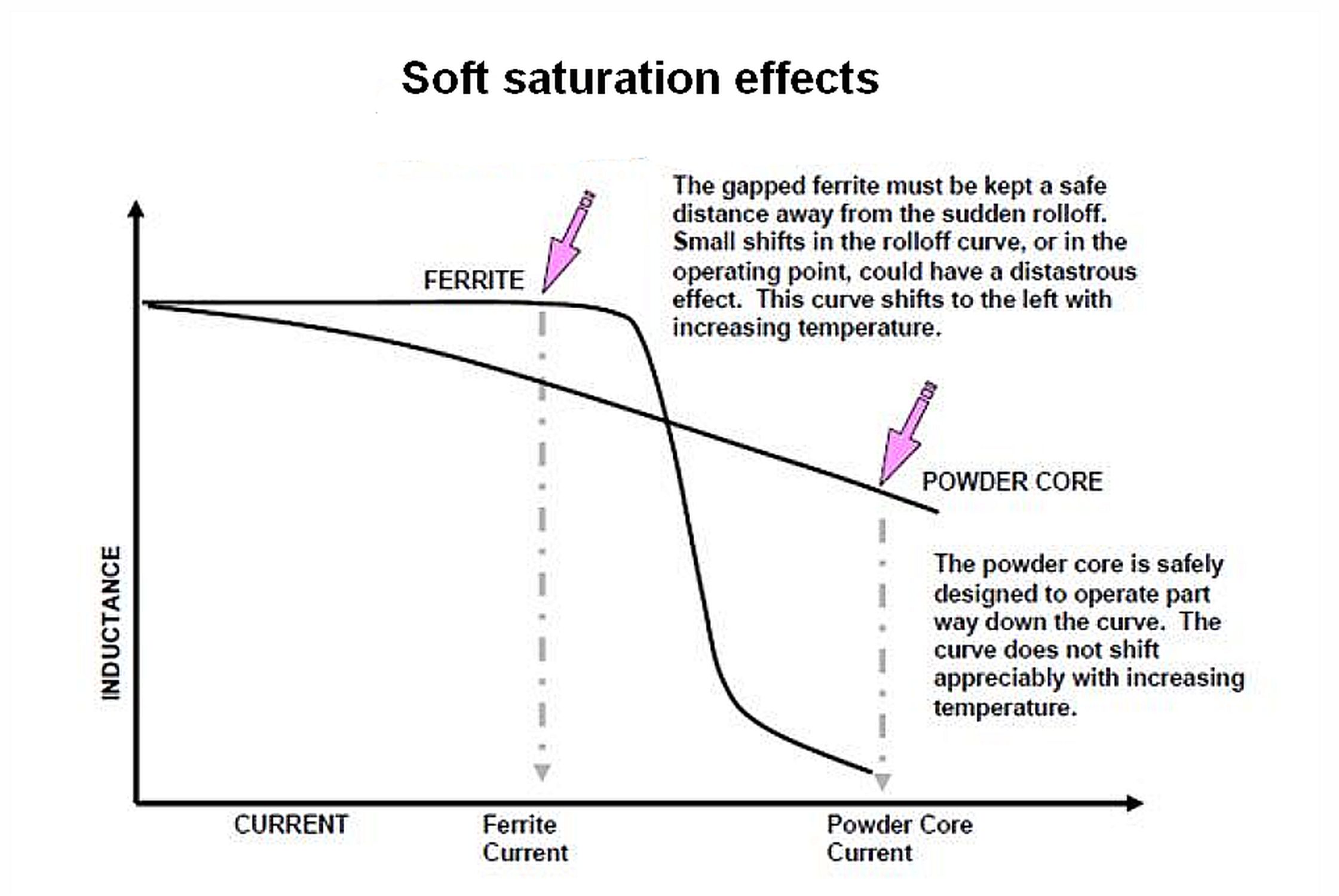
Coilcraft notes that ferrite core inductors have very flat inductance versus current curves until a knee, after which inductance drops off rapidly. Powdered iron and composite core inductors have softer, more gradually sloping saturation curves.
| Core Material | Typical Bsat | Saturation Style | Best Use |
|---|---|---|---|
| Power ferrite | about 0.3 to 0.5 T | Hard knee | High frequency, low loss |
| Iron powder | about 1.0 to 1.4 T | Soft | Low cost chokes, PFC |
| Sendust type | about 1.0 T | Soft | Output chokes, low loss |
| MPP | about 0.75 T | Soft | Precision, low drift |
| Metal composite moulded | about 1 T or more | Soft | Compact buck inductors |
Power Electronic Tips states that commercially useful magnetic materials have Bsat between about 0.3 and 1.8 T. It also notes that ferrites have relatively low Curie temperatures of about 120 to 300 °C, while tape wound and powder cores exceed 450 °C.
For a converter that sees short overload pulses, prefer a soft saturating powder or composite inductor. Its inductance falls gradually, so the controller current limit has time to act.
Ferrite also loses saturation flux density as it warms up, so inductor saturation arrives earlier in a hot product, and an Isat stated at 25 °C can be noticeably lower at 100 °C. Always look for the Isat curve versus temperature, especially for designs in hot Indian control panels.
How Much Does Inductance Drop?
Because makers choose different drop levels, two parts with the same Isat number may behave very differently at that current. A part rated at 30 percent drop will reach only 70 percent of its nominal inductance at its Isat, which raises ripple by about 43 percent.
In a buck converter, a 20 to 30 percent drop at peak current is usually acceptable, since ripple grows but the loop stays stable. Inductor saturation beyond the knee of a ferrite part is not acceptable, because current then rises almost without limit until the switch or controller reacts.
When a ferrite inductor saturates, the triangular ripple current on an oscilloscope bends sharply upward at the end of each on time. Engineers often call this shape a shark fin.
Peak Current Formula for a Buck Converter
Ripple ΔI = (Vin minus Vout) × D ÷ (L × f)
Ipk = Iout + ΔI ÷ 2, required Isat ≥ 1.3 × Ipk
Example:
Vin = 12 V, Vout = 5 V, Iout = 3 A, L = 10 µH, f = 500 kHz
D = 5 ÷ 12 = 0.417
ΔI = 7 × 0.417 ÷ (0.00001 × 500000) = 0.58 A
Ipk = 3 + 0.29 = 3.29 A
Required Isat ≥ 1.3 × 3.29 = 4.28 A
The 1.3 factor gives 30 percent margin for load steps, tolerance and temperature, and Passive Components Blog suggests a range of 20 to 50 percent above expected peak. Duty cycle comes from the PWM duty cycle of the switch, and the same method applies to a boost converter with its own ripple formula.
Inductor Saturation Calculator
Use the worst case input voltage for ripple, which is the highest input for a buck stage. Also enter the lowest inductance after tolerance, often 20 percent below nominal, to see the real peak current.
Second Example: Short Circuit and Start Up
During start up or an output short, current can rise to the controller current limit, a common trigger for inductor saturation. If the switch current limit of the controller is 5 A, an inductor with 4.28 A Isat may saturate before the limit trips.
In such cases choose Isat above the current limit, or pick a soft saturating part whose inductance only falls gradually. Large inrush effects in magnetics are also seen in transformer inrush current, where the core is driven into saturation at switch on.
Symptoms of Inductor Saturation on a Board
Measure the inductor current with a current probe on a fast oscilloscope, and look at the shape of every ramp. A straight ramp shows healthy operation, while a curving ramp near the peak shows inductor saturation has started.
The MOSFET usually suffers first, since its MOSFET conduction loss rises with the square of current. A snubber cannot help here, because the problem is excess current rather than voltage ringing.
If you suspect inductor saturation but have no current probe, add a small sense resistor in series and view its voltage. Keep the resistor value low so it does not change the circuit.
7 Smart Steps to Select an Inductor
These steps work for buck, boost and flyback converters, and for chokes in a boost PFC circuit. In a flyback the transformer must store energy, so the air gap is chosen to avoid inductor saturation at the peak primary current.
- Stable inductance and predictable ripple.
- Lower switch and diode stress.
- Safe start up and overload behaviour.
- Cooler, longer lasting converter.
- Larger inductors take more board space.
- Higher Isat parts may cost more.
- Soft cores can have higher core loss.
- More turns raise DC resistance.
Board Level Tips and Checks
- Confirm peak current at maximum input voltage and full load.
- Read the Isat and Irms definitions on the datasheet.
- Check Isat at the expected core temperature.
- Keep the inductor away from hot parts and use copper pours.
- Verify the current waveform with a current probe.
- Test start up into full load and output short circuit.
Good copper area and thermal vias keep the inductor cooler, which helps both Irms and Isat. A shielded part also reduces stray fields, while a ferrite bead on a supply rail should never carry DC near its own saturation current.
Coilcraft Inductor Specification Guide
Video on Saturation Current
Inductor Saturation FAQ
It is the state in which the magnetic core cannot hold more flux, so inductance drops as current rises. The part then limits current much less than the design assumes.
In switching converters, inductor saturation causes sharp current peaks, hot switches and higher output ripple. Severe saturation can destroy the switch or diode in a short time.
Isat is the current at which inductance falls by a stated percentage, such as 20 or 30 percent. It is a magnetic limit linked to the peak current in the circuit.
Irms is the current that causes a stated temperature rise from losses. It is a thermal limit, so both ratings must be checked in every design.
It depends on the maker, and common definitions are 10, 20 or 30 percent below the low current value. Coilcraft shows all three points on many of its datasheets.
Always read the inductor saturation definition before comparing two parts from different makers. A 30 percent part will have only 70 percent of its nominal inductance at the rated current.
Powdered iron, sendust and metal composite cores saturate softly with a gradual drop in inductance. Ferrite stays flat up to a knee and then drops quickly.
Soft cores suit circuits with overload pulses or fault currents, where sudden inductor saturation would be dangerous. Ferrite suits high frequency designs that need low core loss and a stable value.
For a buck converter, peak current equals load current plus half the ripple current. Ripple equals input minus output voltage, times duty cycle, divided by inductance times frequency.
With 12 volts in, 5 volts out, 3 amperes, 10 microhenry and 500 kHz, the peak is about 3.29 amperes. Add margin to get the required Isat.
A margin of 20 to 50 percent above the calculated peak current is common practice. A factor of 1.3 is a good starting point for most buck designs.
Increase the margin for hot environments and ferrite parts, since heat brings inductor saturation closer. Also cover the controller current limit if start up or short circuit can reach it.
Measure inductor current with a current probe or a small sense resistor and an oscilloscope. A healthy ramp is straight, while a saturated one bends sharply upward near the peak.
Hot switches and current limit trips at low load are further clues of inductor saturation. Test at full load, at start up and with the output shorted.
Related Articles
- Inductor Working Principle
- Buck Converter Working Principle
- Boost Converter Working Principle
- Eddy Current Loss and Hysteresis Loss
- Flyback Converter Working Principle Explained
External References
- Getting Started, An Introduction to Inductor Specifications, Coilcraft
- Comparing Magnetic Cores for Power Inductors, Power Electronic Tips
- Saturation (Magnetic), Wikipedia
What We Learn Today
- Inductor saturation happens when the core nears its maximum flux density, so inductance drops and current rises steeply in a switching converter.
- Isat marks a 10, 20 or 30 percent inductance drop, while Irms marks a temperature rise, so peak and RMS current need separate checks.
- For a buck stage, peak current is load current plus half ripple, and a 1.3 margin gives a required Isat of 4.28 A here.