
A tiny lossy component that turns unwanted high frequency noise into heat while letting DC pass almost untouched.
A ferrite bead is a passive component that blocks high frequency noise by acting as a frequency dependent resistor. Used well, it cleans power rails and signal lines, but used badly it can make noise worse.
What Is a Ferrite Bead?
A ferrite bead is a small piece of lossy ferrite material around a conductor that presents high impedance to high frequency current. It is one of the simplest tools against electromagnetic interference.
At low frequency it behaves like a small inductor with low resistance. Near its rated frequency range it becomes mostly resistive, turning noise energy into heat instead of reflecting it.

Beads are specified by impedance at 100 MHz, such as 600 Ω at 100 MHz. That single number hides a full curve, which is where many design mistakes start.
Unlike a common mode choke, a single bead acts on the whole current in one conductor. It filters differential noise on a supply or signal line.
How the Impedance Curve Works
Altium shows a TDK example with peak impedance near 470 Ω around 200 MHz. The useful filtering band is the resistive region around that peak.
Below the resistive region, the bead is mostly an inductor. There it can form an LC circuit with nearby capacitors rather than a lossy filter.
Always read the full impedance curve in the datasheet, including curves at your DC current. The headline 100 MHz value alone is not enough.
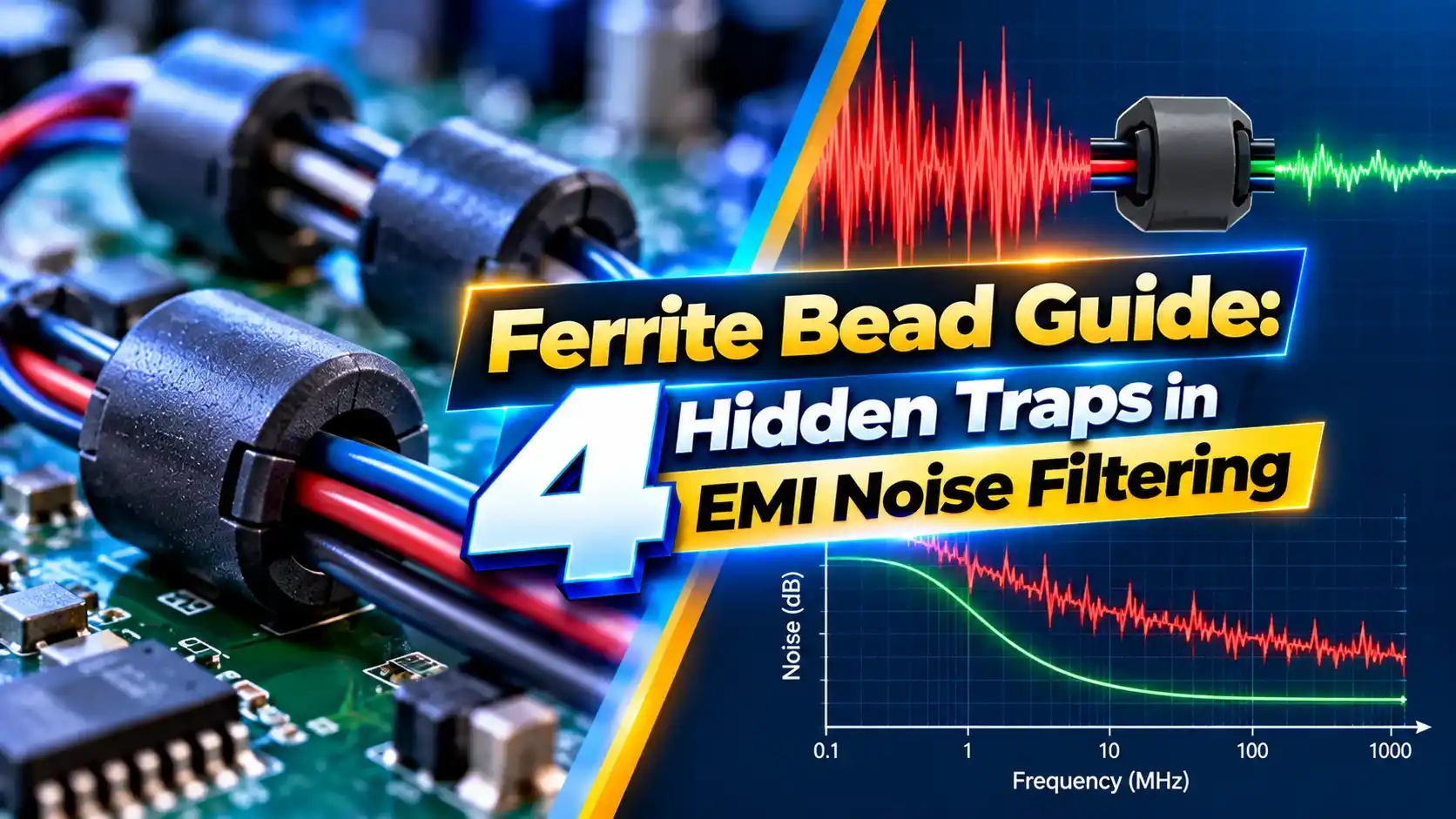
4 Hidden Ferrite Bead Traps in EMI Filtering
Trap 1 catches many designers. A bead that measures 600 Ω unloaded may offer only a small fraction of that when carrying hundreds of milliamps.
Trap 2 appears when a bead feeds a large capacitor. Our guide on decoupling capacitors explains how capacitor choice affects the rail impedance.
Resonance and Voltage Drop Formula
Voltage drop = I × DCR
Worked example:
Low frequency bead inductance L = 1 µH
Output capacitor C = 10 µF
f = 1 ÷ (2π × √(1 × 10 × 10^(minus 12))) = 1 ÷ (2π × 3.16 µs)
f ≈ 50 kHz, close to many switching regulators
Load 500 mA, DCR = 0.1 Ω
Voltage drop = 0.05 V
A resonance near a switching frequency can make noise worse instead of better. Adding a small series resistance or a damping capacitor with ESR reduces the peak.
For switching regulators, compare the resonance with the converter frequency, discussed in linear vs switching regulators.
Types of Ferrite Components
Small surface mount parts for PCB power and signal lines.
Ferrite sleeve on a wire lead.
Split core that snaps over a cable.
Toroid with turns wound through it.
Clamp on ferrites are quick fixes during EMC testing. Looping the cable through twice increases impedance roughly four times at low frequency.
For signal cables, combine ferrites with good cable practice from shielded and twisted pair cables.
Where a Ferrite Bead Helps Most
Analog supplies to an ADC are a classic use. Clean supply rails improve accuracy, as covered in ADC working principle.
Altium warns against beads on GHz digital power delivery, feedback loops and motor supplies. In these places the bead can starve fast transients or destabilize control.
Bead Resonance Calculator
If the resonance lands near a noise source frequency, change the capacitor or add damping. Keep the voltage drop within the load tolerance.
- Small and inexpensive.
- Dissipates noise as heat instead of reflecting it.
- Passes DC with little loss.
- Easy to add during layout or testing.
- Impedance falls with DC current.
- Can resonate with capacitors.
- Only effective in a limited band.
- Adds DC drop and heat.
Ferrite Bead Design Article PDF
Ferrite Bead Basics Video
Ferrite Bead FAQ
Related Articles
- What Is Electromagnetic Interference
- EMI vs EMC Differences
- How Decoupling Capacitors Work
- Common Mode Choke Working Principle
- Noise Reduction Techniques for Digital ICs
External References
- Beads Demystified, Analog Devices
- How Beads Work and How to Choose, Altium
- Using Beads to Reduce EMI, Altium
- Ferrite Bead, Wikipedia
What We Learn Today
- The bead is a lossy, frequency dependent resistor for high frequency noise.
- DC bias and resonance with capacitors are the biggest hidden traps.
- Always read the full impedance curve at your operating current.