
Nearly every phone charger and small isolated power supply relies on the flyback converter working principle, storing energy in a transformer during one half cycle and releasing it during the other.
The flyback converter working principle stores energy in a coupled inductor while a primary side switch is on, then releases that stored energy to the secondary side once the switch turns off, providing isolation between input and output.
This builds on our existing coverage of the buck converter and boost converter, both non isolated topologies unlike this one.
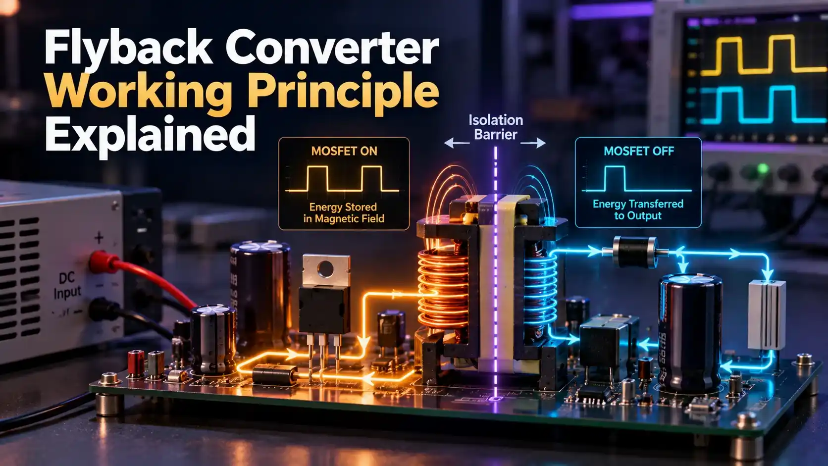
The Core Flyback Converter Working Principle
A flyback converter uses a coupled inductor, often called a flyback transformer, with a primary winding connected through a switch to the input source and a secondary winding connected through a diode to the output.
When the switch turns on, current ramps up in the primary winding, storing energy in the transformer's magnetic core while the secondary side diode stays reverse biased and blocks any current flow.
When the switch turns off, the stored magnetic energy reverses polarity across the windings, forward biasing the secondary diode and releasing that stored energy into the output capacitor and load.
A Simple Numeric Walkthrough
Suppose the switch stays on for 40 percent of each cycle at a 100 kilohertz switching frequency, storing energy in the transformer core for that fraction of each 10 microsecond period.
During the remaining 60 percent of the cycle, that stored energy discharges through the secondary winding and diode into the output capacitor, with the exact voltage delivered set by the transformer's turns ratio.
Why It Is Called a Two Winding Inductor, Not a True Transformer
Unlike a conventional transformer that transfers energy continuously through mutual coupling while both sides conduct, this component only transfers energy during the off period, functioning more like two coupled inductors than a true transformer.
This distinction matters for the core material selected, since the core must be designed with an air gap to store energy without saturating, unlike a standard transformer core optimized purely for magnetizing efficiency.
Key Components
| Phase | Switch State | What Happens |
|---|---|---|
| Energy storage | Switch closed | Primary current ramps up, secondary diode blocked |
| Energy release | Switch open | Secondary diode conducts, energy transfers to output |
| Continuous mode | Cyclical | Some core energy remains before the next cycle begins |
| Discontinuous mode | Cyclical | Core fully discharges before the next cycle begins |
Why Isolation Matters
The transformer's two separate windings provide galvanic isolation between input and output, meaning no direct electrical connection exists between the mains side and the low voltage output a user might touch.
This isolation is a safety requirement for most mains powered chargers and adapters, and it is the main reason this topology is chosen over a simpler non isolated buck converter design for that application.
Feedback and Regulation
An optocoupler often carries feedback from the isolated secondary side back to the primary side controller, preserving isolation while still allowing the controller to adjust switch timing based on actual output voltage.
Without accurate feedback, output voltage would drift as load or input voltage changes, since the open loop relationship between switch timing and output voltage is not precise enough on its own.
Turns Ratio and Output Voltage
The ratio of secondary to primary turns, combined with switch on time, determines the output voltage, giving a designer flexibility to step voltage up or down while maintaining isolation.
Multiple secondary windings can be added to the same core, letting a single flyback design produce several different isolated output voltages from one switching stage.
Continuous vs Discontinuous Conduction Mode
Efficiency and Thermal Considerations
Switching losses in the primary switch and conduction losses in the output diode are the two largest sources of wasted power in a typical design, both worth careful attention during component selection.
Replacing the output diode with a synchronous MOSFET rectifier can meaningfully improve efficiency in higher current designs, at the cost of added control complexity to drive that second switch correctly.
Adequate heatsinking or PCB copper area for both the switch and rectifier keeps junction temperatures within a safe range, extending component life and maintaining stable output over the product's operating lifetime.
Flyback vs Buck and Boost Converters
Flyback Converter
Provides isolation and multiple outputs from one stage, but with more design complexity.
Buck or Boost Converter
Simpler and more efficient, but offers no galvanic isolation between input and output.
The flyback converter working principle earns its extra complexity specifically where isolation and multiple outputs are required, applications a simple non isolated design cannot satisfy.
Selecting Components for a New Design
Choosing the transformer core size and turns ratio starts with the required output power, input voltage range, and desired switching frequency, since these together determine how much energy must be stored each cycle.
Switch voltage rating must account for both the reflected output voltage and the leakage inductance spike, typically leaving healthy margin above the calculated worst case stress the switch will see.
Output capacitor selection balances ripple current rating against physical size, since this component must absorb the pulsed current characteristic of this topology rather than the smoother current a continuous supply would provide.
Common Mistakes to Avoid
Where This Design Shows Up
Phone and laptop chargers rely on this design almost universally at power levels up to a few dozen watts, valuing its low component count and inherent isolation above raw efficiency.
Standby power supplies inside larger industrial equipment often use this same design to generate a small isolated auxiliary rail that powers control circuitry even while the main power stage is off.
LED driver circuits frequently use it as well, since the isolation requirement for many lighting applications rules out simpler non isolated topologies entirely.
Watch: How a Flyback Converter Works
Flyback Converter Working Principle FAQs
Related Articles on This Site
- Buck Converter Working Principle
- Boost Converter Working Principle
- What Is a MOSFET, Working Principle
- Linear vs Switching Voltage Regulators
- Diode Rectifier Circuits
External References
What We Learn Today
- Energy is stored in a coupled inductor while the switch is on, then released when it turns off.
- Separate windings provide galvanic isolation between input and output, unlike a buck or boost design.
- A snubber circuit and correctly gapped core are essential to protect the switch and avoid saturation.