
Drive an ordinary induction motor slightly faster than its synchronous speed and it quietly starts pushing power back into the supply. That simple trick powers wind farms, small hydro plants and regenerative cranes across India.
An induction generator is simply an induction machine whose rotor is driven above synchronous speed. It needs reactive power from the grid or from capacitors, but it is rugged, cheap and easy to connect.
What Is an Induction Generator?
An induction generator is an asynchronous AC machine that converts mechanical power into electrical power when its rotor is driven faster than the speed of the rotating magnetic field. Its construction is the same as the squirrel cage machine described in how an AC induction motor works, so the same frame can motor or generate.
Unlike an alternator, it has no DC field winding and no exciter. The magnetic field is created by reactive current drawn into the stator, which is the key difference from the alternator working principle used in DG sets and power stations.
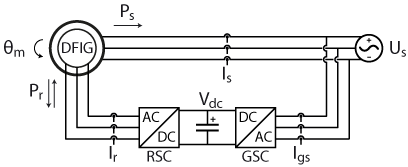
The figure shows the most advanced form, the doubly fed machine used in modern wind turbines. We will build up to it step by step, starting with the plain squirrel cage machine on the grid.
How Negative Slip Produces Power
In motor mode the rotor always turns a little slower than the stator field, and this difference, called slip, induces rotor currents by Faraday law of electromagnetic induction. The rotor currents then produce torque in the direction of rotation.
If a prime mover pushes the rotor above synchronous speed, the rotor now overtakes the field and the slip becomes negative. The induced rotor currents reverse, the torque opposes the prime mover, and active power flows out of the stator into the supply.
Slip s = (Ns minus N) ÷ Ns
s greater than 0: motor, s less than 0: generator
Example, 4 pole machine on 50 Hz grid, rotor at 1530 rpm:
Ns = 120 × 50 ÷ 4 = 1500 rpm
s = (1500 minus 1530) ÷ 1500 = minus 0.02
Slip = minus 2 percent, the induction generator exports power
Typical generating slip is small, about the same magnitude as the rated motor slip explained in induction motor slip. A 4 pole machine rated for 1470 rpm as a motor will usually deliver rated output near 1530 rpm as a generator.
An induction generator needs no synchronising before closing onto the grid. If the rotor speed is near synchronous speed, the machine simply starts motoring or generating depending on which side of synchronous speed it is.
Slip and Output Speed Calculator
Torque and Slip Across Three Operating Regions
| Region | Slip range | Rotor speed | Power flow |
|---|---|---|---|
| Braking | Greater than 1 | Reverse direction | Electrical and mechanical both into losses |
| Motoring | 0 to 1 | Below synchronous | Electrical in, mechanical out |
| Generating | Less than 0 | Above synchronous | Mechanical in, electrical out |
The torque slip curve is roughly mirror shaped on both sides of synchronous speed, with a pull out torque in each region. If the prime mover torque exceeds the generating pull out torque, the machine overspeeds, so turbines need their own speed control and a mechanical brake.
The same physics appears in lifts, cranes and downhill conveyors driven by a VFD, where an overhauling load makes the motor generate. The drive then dumps the energy into a braking resistor or returns it to the supply.
4 Smart Types of Induction Generator
Fixed speed machine that takes magnetising current from the grid and runs just above synchronous speed.
Stand alone machine that builds voltage from residual magnetism with capacitors across the stator.
Slip rings or electronics change rotor resistance to allow a few percent of speed variation.
Wound rotor fed by back to back converters so speed and reactive power can be controlled.
The first two types have no power electronics in the main path, so they are cheap but their voltage and frequency depend on the grid or on the capacitor and load. The last two types add control over speed and reactive power, which modern grid codes require.
Why Reactive Power Is Always Needed
Every such machine consumes reactive power, even while it exports active power, because its air gap flux must be magnetised from the stator side. On the power triangle of active, reactive and apparent power, it delivers kW but absorbs kVAR.
A grid connected machine takes this kVAR from the network, which lowers the power factor at the point of connection. Wind farms and small hydro plants therefore install switched capacitors, sized the same way as a capacitor bank for power factor correction.
Never leave large fixed capacitors connected when a grid connected machine is tripped off the network. The capacitors can self excite the still spinning rotor and produce dangerous overvoltage on the isolated section.
Self Excited Machine and Capacitor Sizing Example
A self excited machine starts with the small residual magnetism in its rotor iron. As the rotor spins, this weak flux induces a small stator voltage, the capacitors draw a leading current, that current strengthens the flux, and the voltage builds up until magnetic saturation stops it.
As a starting point, the capacitors must supply at least the no load magnetising kVAR of the machine. Suppose a 415 V motor draws a no load current of 4 A, so Q is about √3 × 415 × 4 = 2875 VAR, taking the no load current as almost purely reactive.
For delta connected capacitors, C per phase = Q ÷ (3 × 2π × f × V²) = 2875 ÷ (3 × 314.16 × 415²), which is about 17.7 µF. Extra capacitance is then added for the lagging load, and the star and delta connection choice changes the value by a factor of three.
The voltage of a self excited machine falls as load rises and its frequency drifts with speed, so it suits resistive loads such as heaters and lighting. Starting a large motor from it can collapse the voltage, because the motor inrush demands far more kVAR than the capacitors can supply.
Loss of residual magnetism is a common reason a self excited machine refuses to build voltage. Briefly applying a battery across one stator winding while the rotor is stationary usually restores it.
Doubly Fed Machines in Wind Turbines
In a doubly fed induction generator, the stator connects directly to the grid while the wound rotor connects through slip rings to a back to back converter. The rotor side converter injects currents at slip frequency, so the machine can generate over a wide speed range.
Fletcher and Yang of the University of Strathclyde explain that the converters need to handle only the rotor power, typically about 30 percent of the nominal generator power, with a speed range of about ±30 percent around synchronous speed. Their grid side converter can also generate or absorb reactive power for voltage support.
Imperix describes a 2 MW DFIG example in which the rotor and grid side converters are rated at only 500 kW, a quarter of the generator rating. This partial rating is the main cost advantage over a full converter machine, which uses an inverter for the entire output.
Induction Generator Versus Synchronous Generator
| Feature | Induction Generator | Synchronous Generator |
|---|---|---|
| Excitation | Reactive power from grid or capacitors | DC field with exciter and AVR |
| Speed | Varies slightly above synchronous | Locked to grid frequency |
| Synchronising | Not needed | Required before closing |
| Reactive power | Absorbs kVAR | Can supply or absorb kVAR |
| Maintenance | Very low for squirrel cage | Brushes or exciter to maintain |
A synchronous machine controls its own voltage through the excitation system and AVR and needs careful generator synchronizing before paralleling. The induction generator avoids both, which is why it became popular for small, unattended plants.
- Rugged, brushless squirrel cage rotor.
- No DC excitation or synchronising gear.
- Low cost and easy to source as a standard motor.
- Naturally damps torque shocks through slip.
- Always absorbs reactive power.
- Poor voltage regulation when self excited.
- Frequency drifts with speed in stand alone use.
- Cannot easily start large motors off grid.
Applications in Indian Plants and Renewables
Many older fixed speed wind turbines in Tamil Nadu and Gujarat used grid connected squirrel cage machines with capacitor banks at the tower base. Newer turbines mostly use DFIG or full converter designs to meet grid code rules on reactive power and fault ride through.
Commissioning and Troubleshooting Checklist
- Confirm phase rotation matches before first coupling.
- Check rotor speed is above synchronous before expecting export.
- Verify capacitor steps and discharge resistors.
- Set over speed and over voltage protection.
- Measure stator current balance under load.
- Log power factor and kVAR at the connection point.
- For self excited sets, confirm residual voltage at no load.
If the machine motors instead of generating, the prime mover is not reaching synchronous speed or the phase sequence is wrong. Harmonic distortion from converters and capacitors can also cause heating, as explained in power harmonics explained.
Use a soft starter or a speed controlled turbine to bring the rotor close to synchronous speed before closing the breaker. This avoids the large inrush that a direct connection from standstill would cause.
The soft starter working principle article explains how thyristors limit that inrush, and the same devices are fitted on many fixed speed wind turbines for smooth grid connection.
Strathclyde DFIG Reference Paper
Induction Generator Video Lesson
Induction Generator FAQ
An induction generator is an induction machine driven above its synchronous speed so that it exports power. Its stator and rotor are the same as those of a normal induction motor.
It has no DC field winding, so it needs reactive power to create its magnetic field. That reactive power comes from the grid or from a capacitor bank.
Slip is defined as synchronous speed minus rotor speed, divided by synchronous speed. When the rotor runs faster than the field, the result becomes a negative number.
The negative sign shows that the rotor currents and the electromagnetic torque have reversed direction. The machine now absorbs mechanical power and sends electrical power into the supply.
It starts with the small residual magnetism left in the rotor iron from earlier use. Capacitors across the stator draw a leading current that steadily strengthens this weak field.
The voltage rises until magnetic saturation of the core stops further growth. If residual magnetism is lost completely, the voltage cannot build up at all without field flashing.
At minimum, the capacitors must supply the no load magnetising kVAR of the machine at rated voltage. More capacitance is then added to cover the lagging load that will be connected.
For a 415 V machine with 4 A no load current, the delta capacitors are about 17.7 µF per phase. Always confirm the final value by testing at rated speed and load.
A doubly fed induction generator has a wound rotor fed through slip rings by a back to back converter. The stator is connected directly to the grid at fixed frequency.
The converter handles only about 30 percent of the rated power but controls speed and reactive power. This makes it a popular and economical choice for large wind turbines.
Yes, a standard squirrel cage motor can generate when driven slightly above synchronous speed. Many micro hydro, biogas and test bench installations use this simple approach successfully.
Output is usually limited to around the motor rating to keep winding temperature safe. You must also add protection for over speed, over voltage and loss of grid.
The machine always absorbs reactive power, which lowers the power factor at the connection point. In stand alone use its voltage and frequency both change with load and speed.
Starting large motors from a self excited set can collapse the voltage completely. Grid connected machines also need switched capacitors and suitable protection relays for safe operation.
Related Articles
- How an AC Induction Motor Works
- Induction Motor Slip Explained
- Alternator Working Principle Explained
- Synchronous Motor Working Principle
- AC Motors and Generators Back EMF
External References
- Introduction to the Doubly Fed Induction Generator for Wind Power Applications, University of Strathclyde
- DFIG Control for Wind Turbines, Imperix
- Induction Generator, Wikipedia
What We Learn Today
- An induction generator is an induction machine driven above synchronous speed, so its slip becomes negative and it exports active power to the supply.
- It always needs reactive power for magnetising, taken from the grid or from capacitors, and self excited sets rely on residual magnetism to build voltage.
- A doubly fed machine controls speed and reactive power with a rotor converter rated at only about 30 percent of generator power.