
Table of Contents
ToggleCurrent Transformer (CT): Introduction
In every electrical power system, accurate current measurement is very important for protection, monitoring, control, and energy management. Whether it is a power plant, industrial facility, substation, or commercial building, engineers rely on Current Transformers (CTs) to safely measure large currents flowing through electrical conductors.
A Current Transformer may appear to be a simple device. However, incorrect CT selection, installation, or operation can lead to relay malfunctions, inaccurate metering, equipment damage, and lengthy troubleshooting efforts.
Many power system failures can be traced back to issues such as CT saturation, incorrect polarity connections, excessive burden, or even leaving the CT secondary circuit open.
This article explains how Current Transformers work, their major components, different types, important specifications, and common mistakes engineers should avoid.
What is a Current Transformer (CT)?
A Current Transformer (CT) is an instrument transformer designed to convert high primary current into a smaller standardized current that can be safely measured by electrical instruments and protection devices.
Instead of directly connecting relays and meters to high-current conductors, the CT reproduces the primary current at a lower level while maintaining proportionality.
For example:
- Primary Current = 1000 A
- CT Ratio = 1000/5 A
- Secondary Current = 5 A
This means when 1000 A flows through the primary conductor, the CT delivers 5 A to the connected relay or meter.
The CT also provides electrical isolation between high-voltage power circuits and sensitive secondary equipment.
Why Are Current Transformers Important?
Current Transformers perform several essential functions in electrical systems.
1. Safe Current Measurement
Large currents cannot be directly connected to meters or relays. CTs reduce current to a manageable level for measurement.
2. Protection System Operation
Protective relays depend on CT signals to detect faults and initiate breaker tripping.
3. Energy Monitoring
Energy meters use CT outputs to calculate power consumption accurately.
4. Electrical Isolation
CTs isolate measuring instruments from dangerous system voltages.
5. SCADA and Automation
Modern monitoring systems require accurate current signals from CTs for data acquisition and remote supervision.
Working Principle of a Current Transformer
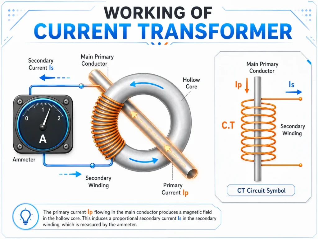
A Current Transformer operates on the principle of electromagnetic induction.
When alternating current flows through the primary conductor, it creates a magnetic field inside the CT core.
This magnetic flux induces a proportional current in the secondary winding.
The secondary current is then supplied to connected devices such as:
- Protection relays
- Energy meters
- Monitoring systems
- Power analyzers
- SCADA equipment
The relationship between primary and secondary currents is determined by the CT ratio.
Example
A CT with a ratio of 500/5 means:
- 500 A primary current produces 5 A secondary current.
- 250 A primary current produces 2.5 A secondary current.
This proportional relationship enables accurate current measurement across a wide operating range.
Main Components of a Current Transformer
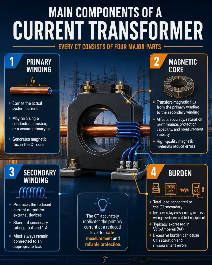
Every CT consists of four major parts.
1. Primary Winding
The primary winding carries the actual system current.
Depending on CT design, the primary may consist of:
- A single conductor passing through the CT
- A busbar
- A wound primary coil
The primary current generates magnetic flux in the CT core.
2. Magnetic Core
The magnetic core transfers magnetic flux from the primary winding to the secondary winding.
The quality of the core directly affects:
- Accuracy
- Saturation performance
- Protection capability
- Measurement stability
High-quality magnetic materials improve CT performance and reduce errors.
3. Secondary Winding
The secondary winding produces the reduced current output supplied to external devices.
Standard secondary ratings are:
- 5 A
- 1 A
The secondary winding must always remain connected to an appropriate load.
4. Burden
Burden refers to the total load connected to the CT secondary.
It includes:
- Relay coils
- Energy meters
- Wiring resistance
- Test equipment
Burden is typically expressed in Volt-Amperes (VA).
Excessive burden can cause CT saturation and measurement errors.
Types of Current Transformers
Different applications require different CT designs.
1. Wound Type CT
In a wound CT, the primary winding is physically wound around the core.
Advantages
1. High accuracy
2. Excellent metering performance
3. Suitable for low-current applications
Applications
1. Precision metering
2. Revenue metering
3. Laboratory testing
2. Bar Type CT
A bar CT uses a solid conductor or busbar as the primary winding.
Advantages
1. Robust construction
2. High current capability
3. Suitable for protection applications
Applications
1. Substations
2. Switchgear
3. Power distribution systems
3. Split-Core CT
A split-core CT can be opened and installed around an existing conductor without disconnecting the circuit.
Advantages
1. Easy installation
2. No system shutdown required
3. Ideal for temporary measurements
Applications
1. Energy audits
2. Retrofit projects
3. Temporary monitoring
Important CT Specifications Every Engineer Must Check
Selecting a CT involves more than choosing the correct ratio.
Several critical parameters must be verified.
1. CT Ratio
The CT ratio defines the relationship between primary and secondary currents.
Examples:
- 200/5 A
- 400/5 A
- 1000/5 A
Incorrect ratio selection results in inaccurate measurements and relay settings.
2. Accuracy Class
The accuracy class specifies the allowable measurement error.
Common metering classes include:
- 0.1
- 0.2
- 0.5
- 1.0
Common protection classes include:
- 5P10
- 10P10
- 5P20
Protection CTs are designed to remain accurate during fault conditions.
3. Burden Rating
Burden indicates the maximum load that can be connected while maintaining accuracy.
Examples:
- 5 VA
- 10 VA
- 15 VA
- 30 VA
Exceeding the burden rating can lead to CT saturation.
4. Knee Point Voltage
The knee point voltage indicates the point at which the CT core begins to saturate.
Protection engineers use this value when designing relay protection schemes.
Higher knee point voltage generally provides better fault-current performance.
5. Short-Time Thermal Rating
During faults, CTs may carry very high currents.
The short-time thermal rating indicates how much fault current the CT can withstand without damage.
Frequently Asked Questions
1. What is a Current Transformer?
A Current Transformer converts high electrical current into a lower, standardized current that can be safely used by meters and protection relays.
2. What are the standard CT secondary ratings?
The most common CT secondary current ratings are 5 A and 1 A.
3. What is meant by CT ratio?
The CT ratio shows the relationship between primary and secondary current. For example, a 1000/5 A CT produces 5 A when the primary current is 1000 A.
4. What is CT burden?
CT burden is the total load connected to the secondary circuit, including meters, relays, wiring, and test equipment. It is expressed in Volt-Amperes (VA).
5. Why should the CT secondary never be left open?
An open CT secondary can generate dangerously high voltage, creating a risk of electric shock, insulation failure, and CT damage.
6. What is CT saturation?
CT saturation occurs when the magnetic core cannot handle additional magnetic flux. This causes inaccurate secondary current and may affect relay operation.
7. What is the difference between metering and protection CTs?
Metering CTs provide high accuracy during normal operation, while protection CTs are designed to reproduce high fault currents accurately.
8. What are the most common CT installation mistakes?
Common mistakes include selecting the wrong ratio, reversing polarity, exceeding the rated burden, using the wrong accuracy class, and leaving the secondary circuit open.
What we learn today?
A Current Transformer may be one of the smallest components in a power system, but its influence is enormous. Every relay decision, meter reading, and operator action depends on the quality of the current signal provided by the CT.
A single mistake such as selecting the wrong ratio, exceeding the burden, reversing polarity, or leaving the secondary open can compromise an entire protection and metering system.
Understanding CT fundamentals helps engineers design safer, more reliable, and more accurate electrical installations.
Remember these four rules:
- Respect the CT ratio.
- Verify the burden.
- Understand the accuracy class.
- Never ignore polarity.
Because in power systems, reliable decisions begin with reliable current measurement.


I hope you like above blog. There is no cost associated in sharing the article in your social media. Thanks for Reading !! Happy Learning