
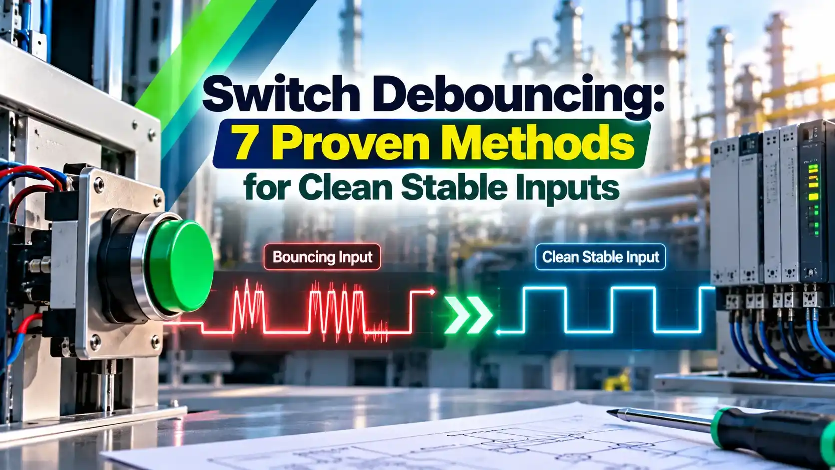
A mechanical contact never closes cleanly, it chatters for a few milliseconds and a fast input sees every chatter as a new press. Good switch debouncing filters that noise so one press always means exactly one event.
Push buttons, limit switches and relay contacts all bounce before they settle. Switch debouncing, with a small circuit or a few lines of code, turns that messy signal into one clean, trustworthy transition.
What Is Switch Debouncing?
Switch debouncing is the technique of removing the rapid, unwanted on and off transitions that a mechanical contact produces when it opens or closes, so that the logic input sees only one clean change of state. It matters for every button, keypad, limit switch and relay contact that feeds a digital circuit.
When two metal contacts meet, they strike, rebound and strike again several times before they rest. A microcontroller that samples in microseconds can read each rebound as a separate press, which makes counters jump and menus skip.
Switch debouncing can be built in hardware, in firmware or in both. Solid state devices described in types of electronic switches do not bounce, so this topic is only about mechanical contacts.
How Long Does a Contact Bounce?
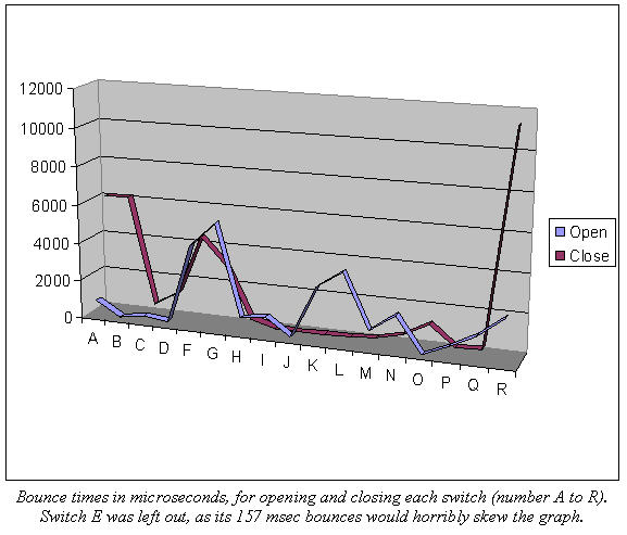
Embedded systems expert Jack Ganssle tested 18 ordinary switches and recorded every bounce on a logic analyser. Sixteen of them showed an average bounce of 1557 microseconds, with a maximum of 6200 microseconds.
Two of the tested switches were much worse, and one produced a bounce of 157 milliseconds while opening. Ganssle also found that two samples of the same switch model could differ by a factor of two.
For this reason most switch debouncing designs treat 1 to 20 milliseconds as the normal bounce window and choose a debounce time a little above the worst case they expect. Old, dirty or worn contacts bounce longer than new ones.
Ganssle observed some bounces shorter than one microsecond when contacts opened. Pulses that narrow can clock a fast flip flop yet remain invisible to a slow multimeter.
7 Proven Switch Debouncing Methods at a Glance
| Method | Type | Parts or Code | Best For |
|---|---|---|---|
| RC plus Schmitt trigger | Hardware | Resistor, capacitor, Schmitt gate | Single buttons, interrupt pins |
| SR latch with SPDT switch | Hardware | Two NAND gates, changeover switch | Clock inputs, lab trainers |
| Debouncer IC such as MAX6816 | Hardware | Dedicated chip | Harsh ESD, many inputs |
| Simple delay | Software | Wait then read again | Quick prototypes |
| Counter or integrator | Software | Periodic sampling, counter | General firmware |
| State machine | Software | Pressed, released, confirm states | Long press and double click |
| Shift register | Software | Bit history in a variable | Compact, fast code |
Hardware switch debouncing cleans the signal before it reaches the logic, which suits interrupt pins and edge triggered circuits. Software methods cost nothing extra on a microcontroller board and can be tuned later.
Hardware Switch Debouncing Circuits
A pull up resistor and capacitor slow the edge, and a Schmitt input squares it again.
A changeover switch sets or resets a latch, and the first touch locks the output.
A chip samples the input and changes the output only after it stays stable.
In the RC circuit, the capacitor cannot follow the fast rebounds, so the voltage rises or falls smoothly. A slow edge on a normal gate can cause oscillation, which is why the gate must have hysteresis, as explained in Schmitt trigger hysteresis.
The SR latch method uses two cross coupled NAND gates, described in latches in digital logic. The moving contact touches the set pin first, the latch flips, and rebounds on that pin cannot flip it back because the contact never reaches the reset pin while bouncing.
The latch needs a single pole double throw switch, so it cannot be used with ordinary two terminal push buttons. The same latch appears in SR, JK, D and T flip flops, where debounced clocks are essential.
Maxim, now part of Analog Devices, makes the MAX6816, MAX6817 and MAX6818 debouncers for one, two and eight switches. Their datasheet states that the output changes only after the input is stable for about 40 milliseconds, with ESD protection of plus or minus 15 kV and a supply current of 6 microamps typical.
Add a small series resistor, around 100 Ω, between the capacitor and the switch contact. It limits the discharge current spike that otherwise erodes contacts and radiates noise.
RC Debounce Time Formula
In the common circuit, a pull up resistor R charges capacitor C toward Vcc when the button is released, and the Schmitt input switches when the capacitor voltage reaches its upper threshold Vth. The charging curve follows the time constant rule in RC and RL time constant.
Discharging, button pressed: t = R2 × C × ln(Vcc ÷ Vth low)
R in kΩ and C in µF give time directly in milliseconds
Example:
R = 10 kΩ, C = 1 µF, Vcc = 5 V, Vth = 3 V
RC = 10 × 1 = 10 ms
ln(5 ÷ (5 minus 3)) = ln(2.5) = 0.916
t = 10 × 0.916 = 9.16 ms
Vth is the upper switching threshold of the Schmitt gate at your supply voltage, taken as 3 V in this example. Always read the real value from the gate datasheet, because it changes with family and supply.
RC Debounce Time Calculator
Second Worked Example: Designing for 20 ms
Suppose a worn panel button bounces for up to 15 milliseconds and you want 20 milliseconds of margin with R = 10 kΩ, Vcc = 5 V and Vth = 3 V. Rearranging gives C = t ÷ (R × ln(2.5)) = 20 ÷ (10 × 0.916) = 2.18 µF.
The nearest standard value is 2.2 µF, which gives t = 10 × 2.2 × 0.916 = 20.16 ms. Check the capacitor tolerance too, because a 20 percent part can shift the delay by the same amount.
Software Switch Debouncing Algorithms
Firmware methods read the pin at regular intervals and accept a new state only after it has been stable for a set time. They work well because a microcontroller already has a timer, as with the delay produced by a 555 timer IC in older discrete designs.
The simplest switch debouncing method waits 20 to 50 milliseconds after the first edge and reads the pin again. It is easy to write, but a blocking delay freezes the rest of the program, so it suits only small prototypes.
The counter or integrator method samples every 5 milliseconds and counts up while the pin is low and down while it is high. The output changes only when the count reaches its limit, so random spikes are averaged away.
The state machine above adds clear states for pressed and released, which makes long press and double click detection straightforward. It is a practical example of the sequential circuits idea written in code.
The shift register method shifts each new sample into a variable, for example 8 or 16 bits wide. A press is accepted only when the history shows a run of identical samples after the old state, which needs just one line of logic per button.
For software switch debouncing, Ganssle recommends sampling in a periodic timer routine instead of attaching the raw switch to an interrupt pin. A bouncing contact on an interrupt can fire dozens of interrupts for a single press.
Choosing the Right Switch Debouncing Time
Encoder and counting inputs need a shorter window, since a real pulse must never be filtered out. Keypads that feed simple logic gates or counters often use 10 to 20 milliseconds.
PLC Input Filters and Industrial Contacts
PLC digital input modules include their own switch debouncing filter, usually adjustable in the hardware configuration. Siemens S7 1200 inputs, for example, offer selectable filter times with a default of 6.4 ms.
Raise the filter when field contacts are old or cables pick up interference, but never above the shortest real pulse, such as an encoder or proximity count. Similar noise issues on analog channels are covered in PLC analog input problems and solutions.
When a PLC counter shows double counts from a mechanical switch, first increase the module input filter. Only move to ladder logic timers if the module filter range is too short.
- One press gives exactly one event.
- Protects counters, menus and interlocks.
- Software options add no hardware cost.
- Hardware options free the CPU and suit interrupts.
- Adds a small delay to every input.
- Wrong time constant can hide real pulses.
- RC parts drift with temperature and age.
- SR latch needs a changeover switch.
Where Switch Debouncing Is Needed
For safety devices, see how emergency stop push buttons use dual channels, where the logic also checks that both contacts change within a set time.
Troubleshooting Switch Debouncing Problems
- Capture a press on an oscilloscope with single shot trigger.
- Confirm the gate input really has Schmitt hysteresis.
- Check that the pull up resistor value matches the design.
- Verify capacitor value and tolerance on the board.
- Look for noise coupled from motors or long cables.
- Confirm the firmware switch debouncing sample rate and count.
- Retest after cleaning or replacing worn contacts.
Noise that arrives on the wiring is not bounce, yet it produces the same false counts. Grounding and filtering advice is covered in noise reduction techniques for digital ICs, and a comparator circuit with hysteresis can clean very slow signals.
MAX6816 Switch Debouncer Datasheet
Contact Bounce Demonstration Video
Switch Debouncing FAQ
It is the removal of the rapid on and off transitions that a mechanical contact makes while opening or closing. The logic then sees only one clean change of state for every press.
Without it, a single press can register several times on a fast input. Counters jump, menus skip and interlock logic can react to signals that never really happened.
Jack Ganssle measured an average of about 1.6 milliseconds and a maximum near 6.2 milliseconds for most of the switches he tested. A few poor switches bounced far longer, with one reaching 157 milliseconds.
Designers therefore plan for a window of roughly 1 to 20 milliseconds. Worn, dirty or cold contacts usually bounce longer than new, clean ones.
The RC network turns sharp rebounds into a slow rising or falling voltage. A normal logic gate can oscillate while such a slow edge crosses its single switching threshold.
A Schmitt input has two thresholds separated by a band of hysteresis. It switches once, ignores small ripple and delivers a clean digital edge to the rest of the circuit.
A changeover switch drives the set and reset inputs of a latch built from two cross coupled NAND gates. The first touch on one side flips the latch immediately.
Rebounds on that same side cannot flip it back, since the moving contact never reaches the other side while bouncing. The method gives an instant and perfect edge with no delay.
The counter or integrator method suits most firmware because it is simple and resists noise well. It samples every few milliseconds and changes state only after steady readings.
A state machine is better when you need long press or double click features. The shift register method is the most compact choice when a board has many buttons to scan.
Most PLC digital input modules already include an adjustable input filter in the hardware configuration. Siemens S7 1200 modules, for example, offer a default filter time of 6.4 milliseconds.
Increase the filter if old field contacts cause double counts in the program. Keep it shorter than any real pulse, such as an encoder or proximity sensor count.
Pick a target time about 1.5 to 2 times the worst bounce you measured. Then use the charging formula with the Schmitt upper threshold to find the capacitor value.
For example, 10 kΩ and 1 µF give about 9.2 milliseconds at 5 volts with a 3 volt threshold. Check component tolerance and temperature drift before finalising the design.
Related Articles
- Schmitt Trigger Hysteresis
- Latches in Digital Logic Explained
- Flip Flop Types SR, JK, D and T
- RC and RL Time Constant Explained
- Noise Reduction Techniques for Digital ICs
External References
- MAX6816 to MAX6818 Switch Debouncers Datasheet, Analog Devices
- A Guide to Debouncing, The Ganssle Group
- Switch and Contact Bounce, Wikipedia
What We Learn Today
- Mechanical contacts usually bounce for about 1 to 20 ms, and Ganssle measured an average near 1.6 ms across most of the switches he tested.
- Switch debouncing can use an RC network with a Schmitt trigger, an SR latch, a dedicated IC or firmware counters and state machines.
- In hardware switch debouncing, the RC release delay is R times C times ln(Vcc ÷ (Vcc minus Vth)), so 10 kΩ and 1 µF give 9.16 ms.