
Two formulas, one for capacitors and one for inductors, control every timing circuit, filter, and switching transient in electronics.
Mix them up and a design that should charge in milliseconds ends up taking seconds instead.
The RC and RL time constant tells you how fast a capacitor or inductor circuit responds to a sudden change in voltage or current, measured in seconds.
Flip a switch in a circuit with a resistor and capacitor, and the voltage doesn't jump instantly. It climbs smoothly along a curve.
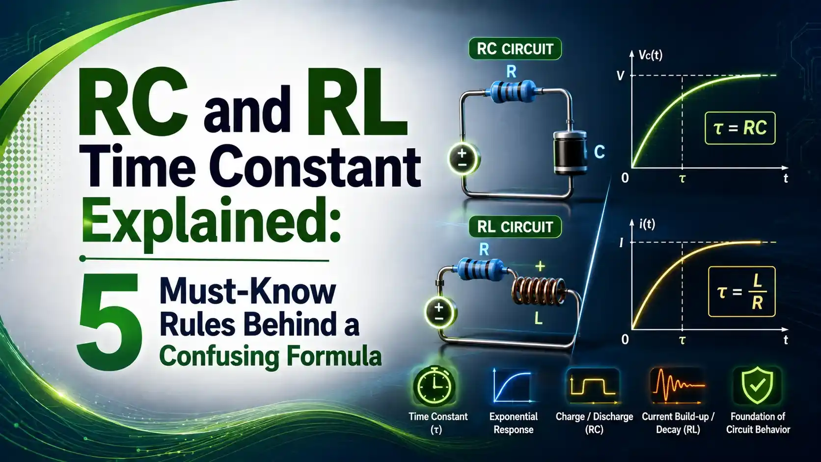
The same thing happens with a resistor and inductor, except current climbs instead of voltage. Both curves follow the exact same shape, a decaying exponential.
The time constant, written as the Greek letter tau, is what sets the pace of that curve. A bigger tau means a slower, lazier response.
The 5 Time Constant Milestones Every Engineer Should Know
Both RC and RL circuits hit the same percentage checkpoints at each multiple of tau.
63.2% Complete
One time constant gets the circuit just under two thirds of the way to its final value.
86.5% Complete
Progress slows noticeably, since the circuit is closing in on its steady state.
95.0% Complete
Often treated as "close enough" for rough timing estimates.
98.2% Complete
The remaining gap is small enough to ignore in most practical designs.
99.3% Complete
The standard engineering rule of thumb for "fully" charged or discharged.
RC Time Constant vs RL Time Constant
Both circuits behave the same way mathematically, but they store energy completely differently.
RC Circuit
Energy stores in a capacitor's electric field. Time constant is resistance multiplied by capacitance.
RL Circuit
Energy stores in an inductor's magnetic field. Time constant is inductance divided by resistance.
Charging vs Discharging Behavior
Charging and discharging are mirror images of each other. One climbs, the other falls, but both use the same tau.
A capacitor never technically reaches the full supply voltage. The exponential curve only gets asymptotically close, which is exactly why the 5 tau rule exists as a practical cutoff.
Time Constant Formulas and Worked Examples
Here are the core formulas, with a worked example for each circuit type.
τ = 10,000 x 0.0001 = 1 second
Charging: Vc(t) = Vs x (1 - e^(-t/τ))
Discharging: Vc(t) = V0 x e^(-t/τ)
τ = 2 / 500 = 0.004 seconds = 4 ms
Energizing: I(t) = (Vs/R) x (1 - e^(-tR/L))
De-energizing: I(t) = I0 x e^(-tR/L)
RC vs RL Circuit Comparison Table
The two circuit types behave identically in shape, but differ in exactly what they store and track.
| Property | RC Circuit | RL Circuit |
|---|---|---|
| Time constant formula | Tau = R x C | Tau = L / R |
| Energy stored in | Electric field (capacitor) | Magnetic field (inductor) |
| Variable tracked | Voltage across capacitor | Current through inductor |
| Behavior at t=0 | Acts like a short circuit | Acts like an open circuit |
| Behavior at steady state | Acts like an open circuit | Acts like a short circuit |
Where RC and RL Time Constants Matter
Timing Circuits
555 timer astable and monostable delay periods.
Audio Filters
Low pass and high pass filter cutoff frequency design.
Camera Flash Circuits
Capacitor discharge timing for flash duration control.
Relay and Solenoid Coils
RL time constant governs coil energizing delay.
Switch Debounce
RC circuits smooth out noisy mechanical switch contacts.
Ignition Coil Systems
RL time constant sets spark energy buildup timing.
Time Constant and Filter Cutoff Frequency
An RC low pass filter's cutoff frequency connects directly back to tau. The two ideas are really the same physics viewed differently.
A larger time constant means a slower time domain response. It also means a lower cutoff frequency in the frequency domain.
Engineers move between these two views constantly. A timing designer thinks in tau and seconds, while a filter designer thinks in hertz, but the underlying RC product never changes.
Common Mistakes With Time Constant Calculations
✓ Do
- Keep units consistent: ohms, farads, henries, and seconds
- Use 5 tau as the practical cutoff for "fully" charged or discharged
- Remember RC multiplies, RL divides
- Check whether the question wants voltage (RC) or current (RL)
✗ Don't
- Assume the capacitor reaches exactly 100% at any finite time
- Mix microfarads into a formula expecting farads without converting
- Forget that inductor current can't change instantaneously
- Confuse a capacitor's initial short circuit behavior with an inductor's
Live RC/RL Time Constant Calculator
Pick a circuit type, enter the component values and elapsed time, and get the time constant plus percent complete.
Reference Materials on RC and RL Time Constants
FAQs on RC and RL Time Constant
External References
- RC Charging Circuit Tutorial and RC Time Constant, Electronics Tutorials
- RC Discharging Circuit Tutorial and RC Time Constant, Electronics Tutorials
- RL Circuit Time Constant, Electrical Academia
- RC and RL Circuits Course Notes, Carnegie Mellon University
- Capacitor Charging and Discharging Curves, Izmir Institute of Technology
What we learn today
- The RC time constant is tau = R x C, while the RL time constant is tau = L / R, both measured in seconds.
- Both circuits follow the same exponential curve, reaching 63.2%, 86.5%, 95.0%, 98.2%, and 99.3% at 1 through 5 tau.
- An RC circuit tracks capacitor voltage, while an RL circuit tracks inductor current, but the math is otherwise identical.
- 5 tau is the standard engineering rule of thumb for "fully" charged, discharged, energized, or de-energized.
- Time constants directly set filter cutoff frequency, timing circuit delays, and coil energizing speed in real designs.