
Every counter, register, and memory cell in digital electronics comes down to one basic building block: the flip-flop. Here is exactly how SR, JK, D, and T flip-flops differ, with real datasheet truth tables and a live simulator you can click through.
What Is a Flip-Flop?
A flip-flop is a circuit with two stable states that stores a single bit of binary data. Unlike a latch, it only changes state on a clock edge, not whenever its inputs move.
The stored bit stays exactly as it is until a deliberate clock transition tells the flip-flop to look at its inputs again. That single property, storing state between clock edges, is what makes flip-flops the memory element behind every counter, shift register, and sequential circuit.

You already met one real application of flip-flops in our guide on PLC shift registers, where a chain of flip-flop style bits tracks parts moving down a conveyor. The same fundamental idea shows up here in four classic flip-flop types: SR, JK, D, and T.
This guide compares all four flip-flop types side by side, using real datasheet truth tables rather than redrawn diagrams, plus a simulator where you can toggle inputs and watch the output respond. Understanding these flip-flop types well is genuinely one of the highest-leverage topics in an introductory digital electronics course.
How a Flip-Flop Stores One Bit
Every flip-flop type follows the same four-step cycle underneath, regardless of how many inputs it has.
Input Conditions Set Up
The data or control inputs (S, R, J, K, D, or T) are driven to whatever values the logic requires.
Clock Edge Triggers a Look
Only when the clock transitions, typically high to low or low to high, does the flip-flop actually read its inputs.
Output Locks to a New State
Based on the input combination, output Q either sets, resets, holds, or toggles, with Q' always the opposite.
State Holds Until Next Edge
That output stays fixed, ignoring any further input changes, until the next valid clock transition arrives.
4 Flip-Flop Types Compared: SR, JK, D, and T
Each of these flip-flop types solves a slightly different problem. Picking the right one comes down to how many inputs you actually need and whether toggle behavior matters.
SR Flip-Flop
The original design, with Set (S) and Reset (R) inputs. Simple, but S=1 and R=1 together produces an undefined, invalid state.
Best for: basic set/reset memory and switch debounce circuits.
JK Flip-Flop
Fixes the SR flip-flop's invalid state. When J=1 and K=1, the output toggles instead of going undefined, earning it the name "universal" flip-flop.
Best for: counters, frequency dividers, and general sequential logic.
D Flip-Flop
Has just one data input, D. Whatever value is on D transfers straight to Q on the clock edge, with no invalid states possible.
Best for: registers, data storage, and input synchronization.
T Flip-Flop
A single toggle input, T. When T=1, the output flips to the opposite state on every clock edge. When T=0, it holds.
Best for: binary counters and clock divider chains.
Real Flip-Flop Datasheet Truth Table
Comparing flip-flop types side by side is much easier once you see a real manufacturer datasheet. Rather than a redrawn diagram, here is an actual datasheet truth table for a JK flip-flop, the kind you would find on a real IC like the Texas Instruments CD74HCT73E.
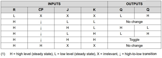
What is happening: The table shows all four possible J and K input combinations, and what the clock transition does to output Q in each case: hold, reset, set, or toggle.
A real example: With J=1 and K=1, the datasheet shows Q simply toggles, flipping to whatever it was not the instant before. That single row is why the JK flip-flop can replace an SR, D, or T flip-flop just by wiring its inputs differently.
Why it works: Because the datasheet spells out every input combination explicitly, there is no ambiguity left for the designer, unlike the SR flip-flop's undefined S=1, R=1 case.
SR Flip-Flop Truth Table
| S | R | Q(next) | Operation |
|---|---|---|---|
| 0 | 0 | Q | Hold |
| 0 | 1 | 0 | Reset |
| 1 | 0 | 1 | Set |
| 1 | 1 | ? | Invalid |
D Flip-Flop Truth Table
| D | Q(next) | Operation |
|---|---|---|
| 0 | 0 | Reset |
| 1 | 1 | Set |
T Flip-Flop Truth Table
| T | Q(next) | Operation |
|---|---|---|
| 0 | Q | Hold |
| 1 | Q' | Toggle |
Flip-Flop Characteristic Equations
Each of these flip-flop types can be written as one compact equation describing its next state.
SR: Q(next) = S + R'Q, valid only when S and R are not both 1
JK: Q(next) = JQ' + K'Q
D: Q(next) = D
T: Q(next) = T⊕Q (T XOR Q)
Worked example: JK flip-flop, Q=0, J=1, K=1
Q(next) = (1)(1) + (0)(0) = 1 (toggled)
Notice the JK equation collapses into the SR equation when J and K never go high together, and collapses into the T equation when J and K are tied together. That overlap is exactly why JK is called the universal flip-flop.
Real Flip-Flop Application: Morse Character Generator
Seeing these flip-flop types inside a genuine working circuit makes the theory click much faster than an isolated symbol.
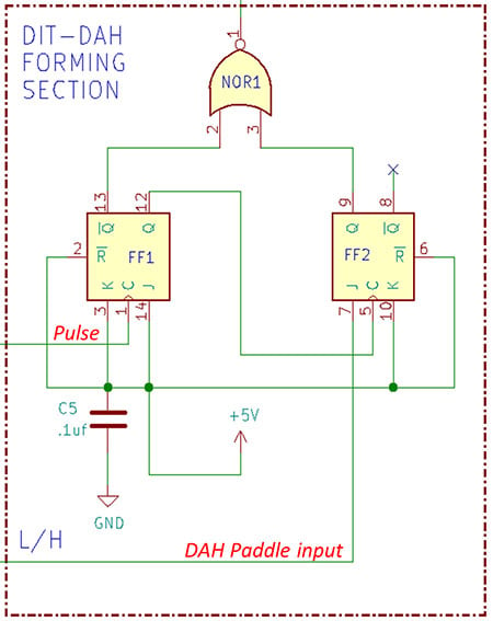
What is happening: Two JK flip-flops, labeled FF1 and FF2, work together with a NOR gate to generate Morse code DIT and DAH characters entirely from digital logic, with no microcontroller involved.
A real example: Pressing the DIT paddle toggles FF1 once. Pressing the DAH paddle sets up FF2 so that FF1 must toggle three full times before the circuit returns to its resting state, producing a signal three times as long as a DIT.
Why it works: Each flip-flop remembers exactly one bit of progress through the character-forming sequence, and the toggling behavior of the JK type is what naturally produces the timed repetition needed for Morse code.
Converting Between Flip-Flop Types
Since JK is universal, it can be wired to behave like any of the other three flip-flop types. Click each tab to see how.
No conversion circuit needed. J behaves exactly like S and K behaves exactly like R, for every input combination except the once-invalid S=R=1 case, which JK simply resolves as a toggle instead.
Connect the D input directly to J, and connect an inverted version of D to K. Whatever value D holds, J and K end up as complementary values, forcing Q to follow D on every clock edge.
Tie the J and K inputs together and treat that single combined connection as the T input. When T is high, both J and K are high, which the JK truth table defines as toggle.
Connect the data input directly to S, and connect an inverted version of it to R. This avoids the SR flip-flop's invalid state entirely, since S and R can never both be 1 at once.
Flip-Flop Comparison Table
This table summarizes all four flip-flop types from the sections above in one place.
| Type | Inputs | Toggle Capable | Invalid State | Best For |
|---|---|---|---|---|
| SR | S, R | No | Yes, S=R=1 | Basic memory, debounce circuits |
| JK | J, K | Yes | None | Counters, general sequential logic |
| D | D | No | None | Registers, data storage |
| T | T | Yes | None | Binary counters, clock dividers |
Applications of Flip-Flops
Different flip-flop types tend to dominate different corners of digital design, based on which behavior each application actually needs.
Binary Counters
Chained T or JK flip-flops toggle in sequence to count clock pulses.
Shift Registers
D flip-flops linked in series move bits one position per clock pulse.
Frequency Dividers
A toggling flip-flop halves the input clock frequency at every stage.
Registers and Memory
D flip-flops hold data bits steady between processor clock cycles.
Switch Debounce Circuits
SR flip-flops clean up noisy mechanical switch contacts into a single transition.
Sequential State Machines
JK and D flip-flops store the current state in traffic light and process controllers.
Advantages and Limitations of Flip-Flop Types
Weighing these flip-flop types against each other usually comes down to whether an undefined input state is acceptable in your design.
Why JK and D Dominate Modern Designs
Limitations to Keep in Mind
Try It: Flip-Flop Simulator
Pick one of the four flip-flop types, set its inputs, then click Clock Pulse to see how the output responds.
Download Flip-Flop References
These two academic references go deeper into flip-flop types, characteristic equations, excitation tables, and sequential circuit design.
Chapter 7: Latches and Flip-Flops
UC Riverside course notes covering SR, JK, D, and T flip-flop theory in depth
Design and Analysis Using JK and T Flip-Flops
University of Cyprus lecture notes with worked design problems
Watch: SR, JK, D, and T Flip-Flops Explained
This video walks through all four flip-flop types with clear truth tables and timing examples.
FAQs on Flip-Flop Types
These questions cover the details about flip-flop types that come up most often for students and engineers alike.
External References
- DigiKey, How JK Flip-Flops Work
- UC Riverside, Chapter 7: Latches and Flip-Flops
- University of Cyprus, Design and Analysis Using JK and T Flip-Flops
- YouTube, Digital Flip Flops Explained: SR, JK, D and T Flip Flop Basics
What we learn today
- The four core flip-flop types, SR, JK, D, and T, all store one bit but differ in inputs, invalid states, and toggle behavior.
- SR flip-flops are simplest but have an invalid state when both inputs are 1.
- JK flip-flops fix that invalid state by toggling instead, and can be wired to emulate SR, D, or T.
- D flip-flops directly copy their input to the output, making them ideal for registers and data storage.
- T flip-flops toggle on every active clock pulse, forming the basis of binary counters and clock dividers.