
A comparator looks almost identical to an op amp on a schematic, yet using the wrong one for a threshold detection job leads to slow, unstable switching that a proper part would never show.
Comparator Circuits compare two input voltages and switch their output high or low depending on which input is larger, a simple job that a dedicated comparator IC does far faster and more cleanly than a general purpose op amp.
Reading about Schmitt Trigger circuits afterward is a natural next step, since hysteresis is the single most common addition made to a basic comparator.
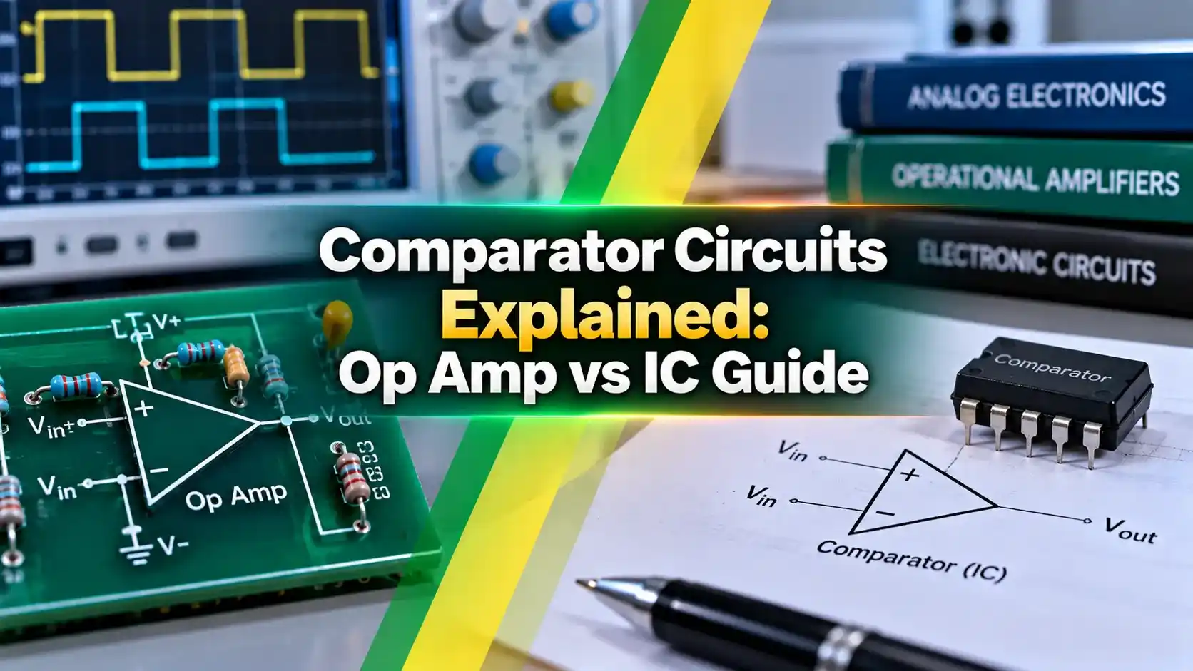
Comparator Circuits Explained
A comparator takes two input voltages, compares them continuously, and drives its output to one rail or the other depending on which input is currently higher.
Unlike an op amp used in a linear feedback configuration, a comparator is meant to operate open loop, swinging hard between its two output states rather than settling at some in between value.
This single function, comparing and switching, underlies everything from a simple battery low indicator to a precision analog to digital converter's internal decision stage.
How a Basic Comparator Circuit Works
Two input pins, typically called the inverting and non inverting inputs, receive the signal being measured and a fixed reference voltage respectively.
When the signal on the non inverting input rises above the reference, the output snaps high, when it falls below the reference, the output snaps low, with no in between state under normal operation.
Many real comparator circuits add a small amount of positive feedback to introduce hysteresis, turning a plain threshold detector into the Schmitt trigger style circuit covered in more detail elsewhere on this site.
Op Amp vs Dedicated Comparator IC
An op amp can technically be wired as a comparator, and for slow, non critical signals this works fine and saves a component on the bill of materials.
A dedicated comparator chip is purpose built for this job, with an output stage designed for fast, clean switching and internal circuitry optimized for speed rather than for linear settling behavior.
Propagation delay on a real comparator IC can be a fraction of what an op amp achieves in the same role, which matters directly in any timing sensitive application.
Key Concepts in Comparator Circuits
| Property | Op Amp Used as Comparator | Dedicated Comparator IC |
|---|---|---|
| Output stage | Analog push pull, slower swing | Push pull, open collector, or open drain |
| Speed | Slower, optimized for linear settling | Fast, optimized for switching |
| Typical parts | LM358, TL081, NE5532 | LM393, LM339, LTC6752 |
| Best for | Occasional, non critical threshold checks | Voltage monitoring, PWM, fault detection |
Common Comparator Circuit Configurations
Common Applications
Common Mistakes in Comparator Circuit Design
Adding Hysteresis to Comparator Circuits
A bare comparator with no feedback switches instantly at a single threshold, which works perfectly for a clean, fast input but poorly for anything slow or riding on noise.
Feeding a small fraction of the output back to the non inverting input creates a second, slightly different threshold depending on which way the output is currently sitting, exactly the hysteresis mechanism used in a Schmitt trigger.
Two resistors set the hysteresis band width, a designer trades some precision about the exact switching point for real immunity against noise sitting on the input signal.
Selecting Resistor Values for Positive Feedback
The feedback resistor ratio, combined with the supply rails, sets exactly how wide the hysteresis band becomes, a wider ratio gives more noise immunity at the cost of a less precise switching point.
Most datasheets for comparator ICs include a worked hysteresis design example, and starting from that reference calculation is far more reliable than guessing resistor values from scratch.
Bench verification with a slow triangle wave input, checked against the calculated upper and lower thresholds on an oscilloscope, confirms the design before it goes into a finished product.
Timing and Response Behavior
Propagation delay is not the only timing spec worth checking, output rise and fall time also matter whenever a comparator drives a fast digital input directly.
A comparator with fast propagation delay but a slow output stage can still bottleneck an otherwise fast signal chain, so both numbers deserve a look on the datasheet rather than just one.
Supply voltage also affects switching speed on many parts, running a comparator closer to its maximum rated supply often measurably improves both propagation delay and output slew rate.
Power Consumption Tradeoffs
Picking between these two families comes down to whether an application values battery life or raw switching speed more, since the two goals generally pull in opposite directions on the same silicon.
Op Amp vs Dedicated Comparator: Quick Guide
Op Amp as Comparator
Saves a part on non critical, slow signals, but propagation delay and output swing are both compromised.
Dedicated Comparator IC
Fast, clean switching purpose built for the job, at the cost of one extra part number on the board.
Any application where switching speed, output drive type, or reliable clean transitions genuinely matter should use a real comparator chip rather than an op amp pressed into service.
Testing and Troubleshooting Comparator Circuits
A stuck output, always high or always low regardless of input, almost always traces back to a missing pull up resistor on an open collector or open drain part rather than a bad chip.
Slow, mushy transitions instead of a sharp edge usually point to excess input capacitance from a long probe lead or an unintended RC filter formed by nearby passive components.
Unexpected chatter around the threshold, even with hysteresis added, deserves a check of actual noise amplitude against the calculated hysteresis band, since real world noise sometimes exceeds initial assumptions.
A Simple Bench Checklist
Working through these four checks in order resolves the overwhelming majority of field issues seen in comparator circuits, long before any chip needs to be replaced as a suspect.
Watch: Comparator Circuit Using LM339
Comparator Circuits FAQs
Across all of these configurations, the underlying idea in Comparator Circuits never changes, compare two voltages, and switch decisively once one clearly exceeds the other.
Related Articles on This Site
- Operational Amplifier Op Amp Basics
- Schmitt Trigger Explained with Applications
- Instrumentation Amplifier vs Op Amp: Key Differences
- Analog to Digital Conversion Explained
- 555 Timer IC Explained
External References
What We Learn Today
- A comparator switches its output between two states based on which input voltage is larger.
- Dedicated comparator ICs beat a repurposed op amp on speed, output type, and clean switching.
- Adding hysteresis turns a basic comparator into a Schmitt trigger, solving noise related chatter.