A transmitter can pass every upscale point and still read high on the way down, and only an up down test shows it. Here you get the percent of span formula, a solved 5 point example, a calculator and a field troubleshooting table.
How to find hysteresis error by comparing upscale and downscale readings at the same test points. We also separate it from deadband and repeatability and show what to fix.
What is hysteresis error in calibration and how is it calculated?
Hysteresis error is the largest difference between the upscale and downscale readings taken at the same test point, divided by the span and multiplied by 100. For example, a 4 to 20 mA transmitter that reads 11.984 mA going up and 12.028 mA coming down at 50 percent has a 0.044 mA gap. On a 16 mA span that is 0.275 percent of span.
What Is Hysteresis Error?
Hysteresis error is the difference in an instrument output at the same input value, depending on whether you reached that input from below (upscale) or from above (downscale). We usually report the largest of these differences as a percent of span, and we can only find it with an up down calibration test.
- Percent of span hysteresis = largest |downscale minus upscale| / span × 100.
- The control.com textbook says it is almost always caused by mechanical friction on a moving element.
- Zero and span trims do not remove a hysteresis error.
If terms like span, zero and accuracy are still new to you, read our instrument calibration common terms first. This post sits next to our guide on zero, span and offset errors, because those adjustments cannot correct hysteresis.
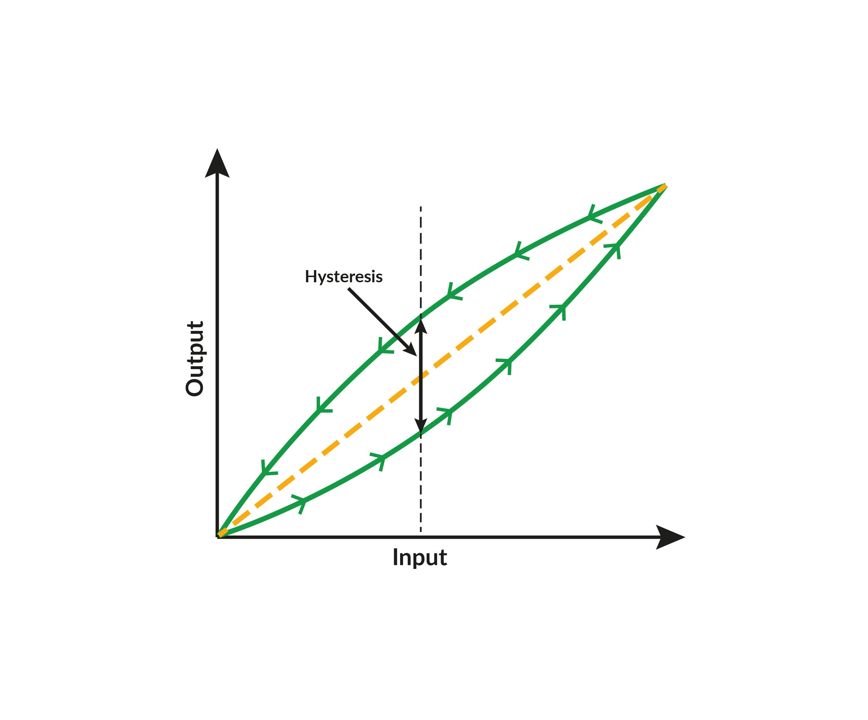
Beamex gives a simple example in that article. A 100 kPa instrument reads 49.95 kPa at the 50 kPa point with rising pressure and 50.05 kPa with falling pressure, so the 0.10 kPa gap is hysteresis, or 0.1 percent of span.
How Do You Calculate Hysteresis Error in Percent of Span?
You calculate hysteresis error by taking the largest gap between the downscale and upscale readings at any single test point, dividing it by the instrument span, and multiplying by 100. Use the same unit for the gap and the span, either output units (mA) or input units (bar, degC).
Hysteresis % of span = Max gap / Span × 100
Span (4 to 20 mA) = 20 minus 4 = 16 mA
In input units: Gap × (Input span / 16 mA)
The control.com textbook works out every calibration error as (measured minus ideal) / 16 mA × 100 for a 4 to 20 mA output. For hysteresis error you compare the two directions with each other instead of with the ideal value.
Keep the sign for the error against the ideal value, which goes into the calibration error calculation on your sheet. Drop the sign for the up down gap that gives the hysteresis error.
If you overshoot a point with the hand pump, do not just bleed back to it. The control.com textbook says to back off and approach the point again from the same direction, otherwise you hide part of the hysteresis.
Solved 5 Point Hysteresis Error Example
Take a 0 to 10 bar pressure transmitter with a 4 to 20 mA output, tested at five points in both directions. The calculator below loads the same readings.
| Point | Input (bar) | Ideal (mA) | Upscale (mA) | Downscale (mA) | Gap (mA) |
|---|---|---|---|---|---|
| 0 % | 0.0 | 4.000 | 4.002 | 4.010 | 0.008 |
| 25 % | 2.5 | 8.000 | 7.990 | 8.020 | 0.030 |
| 50 % | 5.0 | 12.000 | 11.984 | 12.028 | 0.044 |
| 75 % | 7.5 | 16.000 | 15.988 | 16.024 | 0.036 |
| 100 % | 10.0 | 20.000 | 20.006 | 20.006 | 0.000 |
The 100 percent point is the turnaround, so both columns hold the same reading there. The largest gap is at 50 percent.
Span = 16 mA
Hysteresis = 0.044 / 16 × 100 = 0.275 % of span
In bar: 0.044 × (10 / 16) = 0.0275 bar
Limit 0.5 % of span: PASS
With a 0.5 percent of span limit this transmitter passes. With a 0.25 percent limit the same hysteresis error fails it, even though every upscale point is within 0.1 percent.
The Rosemount API 21.1 technical note from Emerson uses an up and down verification sequence of zero, 25, 50, 100, 80, 20 percent and back to zero. Emerson calls hysteresis a non correctable error inherent to pressure measurement devices.
What Is the Difference Between Hysteresis, Deadband and Repeatability?
Hysteresis is an offset between the rising and falling curves, deadband is an input change after a reversal that moves the output not at all, and repeatability is the scatter between runs from the same direction. On one calibration sheet they can look alike, so each needs its own test.
| Property | What you see | How you test it | Typical cause |
|---|---|---|---|
| Hysteresis | Downscale reads high, upscale reads low | Full up down traverse | Friction, elastic after effect |
| Deadband | Output does not move for a small input reversal | Small input reversal at one point | Backlash, loose linkage |
| Repeatability | Same direction readings scatter | Several cycles from one direction | Noise, loose parts, unstable source |
The ISA dictionary defines dead band as the range through which an input signal may vary, upon reversal of direction, without initiating an observable change in output. We cover the switch side of this in deadband in pressure switches, where the gap between set and reset is a design feature.
Beamex says the same: switch deadband looks like hysteresis but is built in to stop the contact chattering. For repeatability, see our post on accuracy and precision.
What Causes Hysteresis in Measuring Instruments?
A hysteresis error mostly comes from friction and from elastic parts that do not spring back exactly as they were loaded. Beamex also lists contamination on moving parts and temperature or humidity changes.
Pivots, links and pointers drag, so the output lags the input both ways.
Bourdon tubes, diaphragms and bellows do not return along the loading path.
The control.com textbook notes that a cracked or bent flexure can also cause hysteresis.
Dirt or process build up on moving parts adds drag.
Friction always acts against the direction of motion. That is why, as the control.com textbook explains, a hysteresis error makes the output read low on a rising input and high on a falling one.
What Is an Acceptable Hysteresis Error Limit?
The acceptable hysteresis error is set by your calibration tolerance, because hysteresis is part of the accuracy the manufacturer states. We compare the largest up down gap with the same percent of span tolerance used for the as found and as left checks.
Emerson Rosemount 3051 data sheets state that reference accuracy includes terminal based linearity, hysteresis and repeatability. Our post on pressure transmitter accuracy specifications explains how to read those figures.
Your reference must be good enough to see the gap. Emerson recommends one at least three times as accurate as the transmitter (API 21.1 asks for two), and our test uncertainty ratio guide shows the check.
How Do You Troubleshoot Hysteresis Error in the Field?
First prove the hysteresis error is real: repeat the up down test, let every reading settle, and check the reference and tubing. If the gap keeps its size and sign, look for the part that drags, bends or slips.
| Symptom | Likely cause | What to do |
|---|---|---|
| Downscale high at every point | Friction in movement or linkage | Clean, lubricate or replace the movement |
| Gap largest at mid range | Elastic after effect of the element | Replace the element if the gap persists |
| Gap changes each cycle | Repeatability or leaking test rig | Leak test the hoses and fittings first |
| Gap appears after overshoot | Test technique | Re approach each point from one direction |
Beamex warns that instrument lag can look like hysteresis, so give each point enough time to stabilise. On a smart transmitter, also check the damping setting before you blame the sensor, as we explain in pressure transmitter damping and response time.
- Same gap and same sign on two or more full cycles
- Downscale reads high and upscale reads low
- Zero and span trims do not change the gap
- Gap changes size or flips sign between cycles
- Gap appears only after you overshoot a point
- Test hoses or the reference source leak
Control valves show the same pattern when packing friction makes the stem lag the signal. See our posts on control valve stiction detection and valve positioner calibration.
Plot input against output for both runs. Beamex notes that hysteresis is hard to see in numbers alone, while the open loop on a graph is obvious.
Video and Reference Document
This Beamex video shows a pressure transmitter calibration with an MC6 calibrator and a hand pump. Watch how the pressure is set at each point, because that decides whether you catch a hysteresis error or hide it.
The Emerson technical note below gives the up and down sequence used for API 21.1 custody transfer work.
Hysteresis Test Checklist
Run through this list before you sign the calibration sheet.
- Reference standard at least three times better than the instrument tolerance
- Each point approached from one direction only, no overshoot
- Upscale and downscale readings recorded at the same five points
- Largest gap converted to percent of span and compared with the limit
- As found and as left results both kept on the certificate
Store both sets of readings, as our guide to the as found and as left calibration certificate explains. A gap that grows between calibrations points to a wearing movement or element.
Hysteresis Error FAQ
Hysteresis error is the gap between readings at one input approached from below and from above. Beamex gives a 100 kPa instrument reading 49.95 kPa going up and 50.05 kPa coming down at 50 kPa.
That 0.10 kPa gap is 0.1 percent of span.
Record upscale and downscale readings at the same points, find the largest difference at any one point, divide it by the span and multiply by 100. A 0.044 mA gap on a 16 mA span gives 0.275 percent.
Keep the gap and span in the same unit.
Hysteresis is a lasting offset between the rising and falling curves across the range. Deadband is the small input change after a reversal that causes no output change at all.
A pressure switch deadband is built in on purpose, while hysteresis in a transmitter is an error you have to fix.
Friction in the movement and the elastic after effect of the Bourdon tube make the pointer lag behind the pressure. On a falling pressure the lag leaves the pointer above the true value.
On a rising pressure the same lag makes it read low.
No, because zero and span shift or tilt the whole curve while hysteresis separates the up and down curves. You have to remove the cause instead.
Clean or replace a sticking movement or fix a bent flexure, then repeat the up down test.
The most common mistake is overshooting a point with the hand pump and bleeding back to it. That reversal hides part of the hysteresis and makes the instrument look better than it is.
Approach each point from one direction, and wait for the reading to settle before you record it.
Related Articles
- Calibration Error Calculation with Percent of Span Formula
- Instrument Calibration Common Terms
- Offset Error, Zero Point Error and Span Error
- Calibration Certificate As Found and As Left Data
- Deadband in Pressure Switches
External References
- Emerson: Calibration of Rosemount DP Transmitters to API 21.1 (PDF)
- Beamex: Hysteresis in pressure calibration, what you need to know
- Wikipedia: Hysteresis
What We Learn Today
- Hysteresis error is the largest gap between upscale and downscale readings at one test point, divided by span and multiplied by 100.
- Only an up down test finds it, and each point must be approached from one direction without overshoot and given time to settle.
- Friction and elastic after effect cause it, so zero and span trims will not fix it; repair or replace the sticking part instead.