A valve only controls well when it takes a fair share of the pressure drop in its circuit. We calculate that share, see what it does to the installed characteristic and use it to choose between linear and equal percentage trim.
Valve authority tells you how much of the loop pressure drop the control valve owns. That one number decides how far the installed curve drifts from the catalogue curve, and you can work it out for your own line with the calculator below.

What is control valve authority and how do you calculate it?
Control valve authority (N) is the share of the circuit pressure drop taken by the fully open valve at design flow: N = ΔPvalve ÷ (ΔPvalve + ΔPrest of system). Aim for at least 0.25 and preferably 0.5 or more. For example, a valve dropping 40 kPa in a loop where the pipe, coil and fittings drop 60 kPa has N = 40 ÷ 100 = 0.40.
What Is Control Valve Authority?
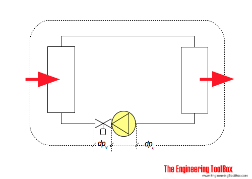
Control valve authority is the ratio of the pressure drop across the fully open control valve to the total pressure drop of the circuit it controls, at design flow. It runs from 0 to 1, and the closer it is to 1, the more the valve, rather than the piping, decides how much flow passes.
- Formula: N = ΔPv ÷ (ΔPv + ΔPs), with both drops taken at full design flow.
- Engineering ToolBox rates 0 to 0.25 as unstable to fair, 0.25 to 0.5 as fair to good and 0.5 to 1.0 as good.
- Belimo and Danfoss both aim for an authority of 0.5 or higher in hydronic circuits.
- Low authority pulls the installed curve away from the catalogue curve.
Control valve authority is what turns the inherent curves in our note on flow characteristics of control valves into the curve you get in the plant.
Vesa Lempinen of Valmet describes high authority as a value close to one, and low authority as the case where pipeline loss is significant compared with the loss across the control valve.
How to Calculate Valve Authority Step by Step
To calculate valve authority, divide the pressure drop across the fully open valve at design flow by the sum of that drop and the drop across everything else in series with it. Both numbers must come from the same flow rate.
ΔPv = drop across the open valve at design flow
ΔPs = drop across pipe, fittings, coil, exchanger
Rearranged for sizing:
ΔPv = N × ΔPs ÷ (1 minus N)
You use the rearranged form during design. Engineering ToolBox gives a heating circuit example where the circuit drops 15 kPa at 1.4 l/s, and a target authority of 0.8 needs a valve drop of 0.8 × 15 ÷ 0.2 = 60 kPa.
Use our pipe pressure drop calculation for the series losses, and the control valve flow coefficient article for how Cv links flow to drop. For a second check, the valve authority calculator on Zenta Calculator gives the same ratio.
Do the calculation again with the Cv of the valve you actually buy. A catalogue size one step larger than the calculated Cv drops less pressure, and authority falls with it.
Why Does Low Authority Distort the Installed Characteristic?
Low authority distorts the installed characteristic because the valve drop does not stay constant: as flow rises, more pressure is lost in the pipe and less is left across the valve. The valve then reaches most of its flow early in its travel and does little near the top.
Danfoss engineers Atli Benonysson and Herman Boysen write that low authority distorts the characteristics of the valve. They add that with an authority above 0.5 the effective characteristics stay very close to the real ones, even without differential pressure control.
q = f ÷ √(N + (1 minus N) × f²)
f = inherent flow fraction at that travel
Linear trim: f = travel
Equal % trim (R = 50): f = 50(travel minus 1)
The table applies that formula at 50 percent travel, with a fixed total drop and no pump curve effect.
| Authority N | Linear trim, flow at 50% travel | Equal % trim (R = 50), flow at 50% travel |
|---|---|---|
| 1.0 | 50% | 14% |
| 0.5 | 63% | 20% |
| 0.25 | 76% | 27% |
| 0.1 | 88% | 39% |
At N = 0.1 a linear valve passes 88 percent of full flow at half travel, so the last half of the stroke adds only 12 percent and loop gain swings widely with load. The equal percentage column moves towards a straight line as authority falls, which is why the two trims suit different loops.
A centrifugal pump makes this worse, because its head rises as flow falls and the valve sees a larger drop at low load. Zenta Engineering covers the centrifugal pump working principle, and our comparison of centrifugal and positive displacement pumps shows why the curves differ.
What Is a Good Control Valve Authority Value?
A good control valve authority is 0.5 or higher, and 0.25 is the practical minimum for a throttling valve. Below 0.25 the installed curve is so distorted that tuning one set of PID gains for the whole load range becomes hard.
Higher authority gives better control but costs pump energy, because every kPa the valve burns at full flow comes from the pump. That is why 0.25 to 0.5 is the usual band, with 0.5 chosen where the extra head is cheap.
The basic requirements of control valve sizing include this check along with travel at minimum and maximum flow. It also ties to control valve rangeability, since a flattened installed curve eats into useful turndown.
Linear vs Equal Percentage: Which Trim Suits Your Authority?
Pick linear trim when the valve takes most of the system pressure drop, and equal percentage trim when it takes a small share. The ISA Ask the Automation Pros panel of March 2025 draws the same line.
Gregory McMillan says there that linear is required when most of the system drop is across the valve, citing pH reagent valves and steam header pressure control. For most other cases he prefers equal percentage, partly for its rangeability at low valve to system pressure drop ratios.
- High authority, where the valve owns most of the drop
- pH reagent valves and steam header pressure, per McMillan
- Loops whose process gain is not inversely proportional to flow
- Low authority, where pipe and equipment take most of the drop
- Jacket, coil and heat exchanger temperature loops, per Mark Darby
- Valves that may turn out oversized or undersized
Darby warns that in a temperature to flow cascade control scheme, an equal percentage valve can add a nonlinearity to the inner loop. Our page on control valve trim types shows the other trim shapes.
Russell Rhinehart notes in the same ISA panel that equal percentage valves typically have a rangeability of about 15 to 50, and a true equal percentage valve cannot shut off.
Solved Example: Control Valve Authority on a Chilled Water Coil
In this example the valve drops 40 kPa at design flow and the coil, pipe and fittings drop 60 kPa, so the control valve authority is 0.40. That sits in the fair to good band, and a linear trim at half travel would pass about 67 percent of full flow.
N = 40 ÷ (40 + 60) = 0.40
Linear trim at 50% travel, f = 0.5:
q = 0.5 ÷ √(0.40 + 0.60 × 0.25)
q = 0.5 ÷ √0.55 = 0.5 ÷ 0.742
q = 0.67, about 67% of full flow
Lifting control valve authority to 0.5 needs ΔPv = 0.5 × 60 ÷ 0.5 = 60 kPa, so a smaller Cv and 20 kPa more pump head.
Enter both drops at the same design flow and the travel you want to check. The calculator returns N, a rating and the installed flow of a linear trim.
The calculator assumes a fixed total drop, so on a pumped loop run it at minimum, normal and maximum flow, as Michel Ruel advises in the ISA panel.
Field Problems Caused by Poor Valve Authority
Poor authority shows up as a valve that does most of its work early in the stroke, hunts at low load and is sluggish at high load. The usual symptoms are below.
| Symptom | Likely cause | What to check or do |
|---|---|---|
| Loop cycles at low load, slow at high load | Low authority on linear trim | Calculate N; consider equal percentage trim |
| Valve runs 10 to 20% open at full load | Valve oversized, low drop | Recheck Cv against real flow; a smaller trim raises N |
| Good control after commissioning, poor later | Strainer or coil fouling added drop | Measure dP across valve and equipment; clean and recheck |
Rule out mechanical faults first, because stick slip near the seat looks like a gain problem. A stiction check and a look at the causes of control valve hunting come first.
Read differential pressure across the valve and across the coil at the same time. Two readings at one flow give you the real authority.
A low authority valve sees a large drop near closure, which raises the risk of control valve cavitation and flashing and choked flow at minimum flow.
- Valve drop and system drop taken at the same design flow
- Authority rechecked with the Cv of the valve actually selected
- N at least 0.25 for every throttling valve, 0.5 where pump head allows
- Trim chosen to suit N: linear for high authority, equal percentage for low
- Pump curve checked for valve drop at minimum flow
A badly set positioner can mimic the same symptoms, so see how a control valve positioner works and how to tune a PID controller too.
Equilibar shows its dome loaded diaphragm valve controlling at an authority below 5 percent. That is a maker showing its own design; Equilibar itself says traditional valves need 25 to 50 percent.
For the full selection workflow, see our control valve selection factors.
Control Valve Authority FAQ
Control valve authority is the share of the circuit pressure drop that the open valve takes at design flow. If the valve drops 40 kPa and the coil and pipe drop 60 kPa, N = 40 ÷ 100 = 0.40.
That means the valve owns 40 percent of the pressure budget.
Take the drop across the open valve and the drop across everything else in series, both at design flow. Then divide the valve drop by the sum of the two.
On a pumped loop, repeat the check at minimum and maximum flow, because the pump head changes with flow.
Belimo and Danfoss both aim for an authority of 0.5 or more on two port valves in hydronic systems. Engineering ToolBox calls 0.25 to 0.5 fair to good and anything below 0.25 unstable to fair, so treat 0.25 as the floor.
The inherent characteristic is measured at a constant pressure drop across the valve on a test bench. The installed characteristic is what you get in the plant, where the valve drop changes with flow.
Authority decides how far the installed curve moves from the inherent one.
Equal percentage is usually the better choice at low authority, because the installed curve bends towards a straight line. Gregory McMillan, writing in the ISA Ask the Automation Pros panel of March 2025, keeps linear trim for cases where most of the system drop is across the valve.
The most common mistake is taking the valve drop and the system drop at different flows, or using the calculated Cv instead of the Cv of the valve actually bought. A larger catalogue valve drops less pressure, so the real authority ends up lower than the design figure.
Related Articles
- Flow Characteristics of Control Valves
- Control Valve Sizing Basic Requirements
- Control Valve Flow Coefficient
- Control Valve Rangeability and Turndown
- Control Valve Selection Key Factors
External References
- Belimo: Selection and dimensioning of control valves, general notes for project planning (PDF)
- Engineering ToolBox: Control Valve Authority
- Wikipedia: Control valve
What We Learn Today
- Control valve authority is the share of design flow pressure drop taken by the open valve, and you calculate it as valve drop divided by total circuit drop.
- An authority of 0.5 or more keeps the installed curve close to the catalogue curve, while values under 0.25 bend it badly and make tuning hard.
- Choose linear trim when the valve takes most of the system drop and equal percentage trim when the pipe, coil or exchanger takes most of it.