
A temperature sensor inside a thermowell reads well only when its tip firmly touches the bottom of the bore. A small spring behind the insert provides that contact, and getting its compression right decides speed, accuracy and sensor life.
The spring behind a thermowell insert looks like a minor detail, yet it controls how fast and how truly the sensor follows the process. This guide explains bore fit, spring travel, vibration and safe insert replacement with worked numbers.

What Is a Spring Loaded RTD?
A spring loaded RTD is a resistance temperature detector measuring insert that is pushed against the bottom of a thermowell by a compression spring, so that the sensing tip keeps firm metal to metal contact with the well. The sensing element itself is usually a Pt100, whose basic working is explained in what is an RTD and how it works.
The thermowell protects the sensor from pressure, flow and corrosion. Even a well designed as described in this thermowell guide, still adds thermal lag, and the spring is there to keep that lag as small as possible.
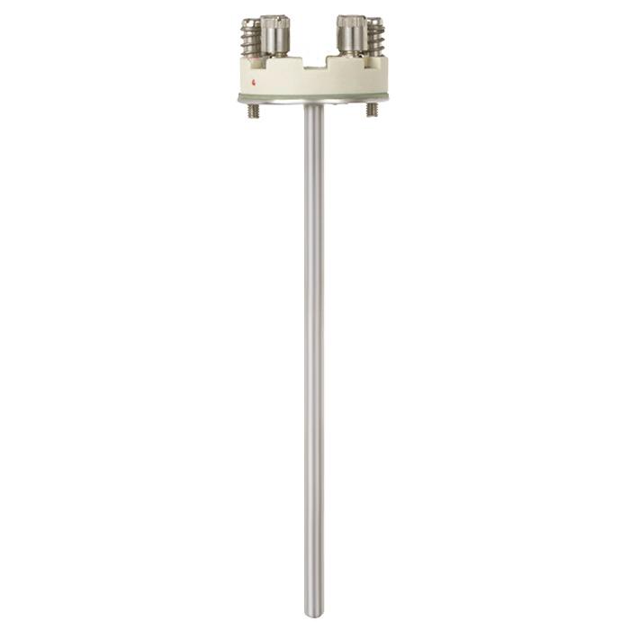
The spring sits between the insert mounting plate and the screws that fix it inside the connection head. When the head is closed on the thermowell, the insert tip meets the bore bottom first, the spring compresses a few millimetres and that stored force keeps the tip seated through heating, cooling and vibration.
Air conducts heat roughly six hundred times worse than stainless steel. A thin air gap of half a millimetre around the sensor tip can therefore slow the reading more than the thick thermowell wall itself.
How the Spring Keeps the Insert Bottomed
Bottoming means the flat or rounded tip of the measuring insert rests against the closed end of the thermowell bore. Heat from the process then flows through the well wall straight into the sensor sheath instead of crossing an air layer.
WIKA states in its TR11 A datasheet that the spring allows a maximum travel of 10 mm to hold firm contact with the thermowell bottom. The same datasheet warns that the bore should be no more than 1 mm larger than the insert diameter, and that gaps above 0.5 mm harm heat transfer.
Without a spring, a rigid probe of fixed length either stops short of the bottom or presses so hard that it bends. The spring absorbs normal length tolerances and thermal expansion, which matters because sheath and well grow by different amounts at high temperature, a point also covered in thermocouple and RTD installation precautions.
Insert Diameter and Thermowell Bore Matching
Measuring inserts built to DIN 43735 come in fixed diameters, and the thermowell bore must be drilled to suit. WIKA offers the TR11 A in 3 mm, 6 mm and 8 mm diameters, and the 6 mm size is the most common choice in process plants.
| Insert diameter | Typical bore | Typical use | Remark |
|---|---|---|---|
| 3 mm | 3.5 mm | Small wells, fast response | Fragile, bends easily |
| 6 mm | 6.5 to 7 mm | General process service | Most widely stocked |
| 8 mm | 8.5 to 9 mm | Robust, high vibration | Slower response |
| Dual element 6 mm | 6.5 to 7 mm | Measure plus backup | Check transmitter channels |
A tight fit gives a spring loaded RTD fast response, but a bore that is too tight can jam the insert when deposits or slight bending appear. A small clearance of about half a millimetre is the usual compromise, and bore details for each style are given in thermowell types explained.
Before ordering a replacement spring loaded RTD insert, measure the real bore depth with a depth gauge or a marked rod. Drawings are often out of date after earlier modifications.
Response Time and the Air Gap
Response time is usually expressed as t50 or t90, the time to reach 50 or 90 percent of a step change. A thermowell adds mass and wall thickness, so a well mounted sensor is always slower than a bare probe, as shown in temperature sensor response time.
The biggest controllable part of that delay is the contact between the insert tip and the bore. A spring loaded RTD that is properly bottomed removes most of the air path, while a floating tip may take many times longer to settle.
Endress+Hauser reports that its QuickSleeve insert, which adds a patented spring element that bridges the radial air gap, gives up to 2 times faster response than a conventional insert in a barstock well. It suits bores of 6.5 mm and 7 mm and temperatures up to 400 °C.
Some sites fill the bore bottom with a little heat transfer paste or oil at low temperatures. It improves contact further, but it must suit the process temperature and never be used where it could coke or burn.
Spring Compression Formula
The spring compression is simply the insert length minus the distance from the insert seat in the head to the thermowell bottom. It must be greater than zero so the tip touches, and smaller than the spring travel so the spring never goes solid.
Remaining travel = T minus C
L = insert length below the mounting plate, mm
D = depth from mounting plate seat to bore bottom, mm
T = maximum spring travel, mm
Example:
L = 315 mm, D = 309 mm, T = 10 mm
C = 315 minus 309 = 6.0 mm
Remaining travel = 10 minus 6.0 = 4.0 mm
Spring Loaded RTD Compression Calculator
Second Worked Example: Old Well, New Insert
A refinery replaces a failed insert in an old well whose bore was measured at 305 mm from the head seat. The stores hold a standard 315 mm insert with 10 mm spring travel, so C = 315 minus 305 = 10 mm and the remaining travel is zero.
The spring loaded RTD would be fully compressed, the plate would not seat and the screws could bend the sheath. The correct action is to order a 310 mm insert, which gives 5 mm compression and 5 mm reserve, or to use a model with longer travel.
Common Spring Loaded RTD Designs
A 6 mm insert with terminal block, held by two screws and springs inside a DIN B head.
A spring sits inside an adapter or nipple union fitting, and the probe screws into the well.
A bayonet cap locks the probe while a spring pushes the tip down.
The insert carries a transmitter on top instead of a terminal block.
With a head mounted transmitter, check the wiring before closing the head, using the 3 wire or 4 wire schemes in RTD sensor connections. Range and sensor type are then set as described in temperature transmitter configuration and ranging.
Vibration and Mechanical Life
A tip that floats inside the bore can rattle against the wall when the line vibrates, and over months this fretting cracks the sheath or breaks the fine element leads. A firmly bottomed spring loaded RTD is supported at both ends, which greatly reduces this movement.
The thermowell itself must also survive flow induced vibration, which is checked with the wake frequency method of ASME PTC 19.3 TW 2016. The spring protects the insert, not the well, so both checks are needed on high velocity lines.
7 Proven Steps to Install a Spring Loaded RTD
Replacing a Measuring Insert Without Shutdown
One of the main benefits of a separate insert is that it can be withdrawn while the plant is running, because the thermowell keeps the process sealed. WIKA lists replacement for maintenance as a primary use of its TR11 A insert.
In a hazardous area, follow the hot work and Ex rules before opening a flameproof head. The head may only be opened after power is off, as explained for Ex equipment.
For Ex d heads and intrinsically safe loops the replacement insert must carry the same or a compatible certificate. The rules are summarised in temperature measurement with hazardous area sensors.
- Firm tip contact gives faster, truer readings.
- Absorbs length tolerance and thermal growth.
- Reduces rattling and fretting under vibration.
- Insert can be replaced without draining the line.
- Needs correct insert length for the well.
- Spring can go solid if the insert is too long.
- Springs lose force at very high temperature.
- Still slower than a direct immersion probe.
Troubleshooting Slow or Wrong Thermowell Readings
- Pull the insert and look for marks on the tip that show contact.
- Measure bore depth and compare with insert length.
- Check the spring moves freely and returns fully.
- Inspect the bore for water, scale or a broken old tip.
- Confirm the bore clearance is no more than about 1 mm.
- Check wiring, lead resistance and transmitter sensor type.
- Compare readings with a reference after a step change.
A slow sensor often looks like a tuning problem, so engineers sometimes detune a loop when the real fault is a spring loaded RTD with a floating tip. Other common error sources, including stem conduction and lead resistance, are reviewed in temperature measurement errors.
When the insert itself is suspect, test it in a dry block calibrator at two or three points. A spring loaded RTD that passes on the bench but reads low in service almost always points to poor contact or a short insert.
Where a Spring Loaded RTD Is Used
WIKA TR11 A Measuring Insert Datasheet
Thermowell and RTD Video
Spring Loaded RTD FAQ
It is an RTD measuring insert pushed against the bottom of a thermowell by a small compression spring. The spring keeps the sensing tip in firm metal contact with the well.
That contact lets heat flow directly from the process into the sensor. The result is a faster and more accurate reading than a probe that hangs loose inside the bore.
The insert length should exceed the seat to bottom depth by a few millimetres. WIKA quotes a maximum spring travel of 10 mm for its TR11 A insert.
A compression of about 3 to 6 mm leaves reserve for thermal growth. Zero compression means no contact, and full compression means the spring has gone solid.
WIKA advises a bore no more than 1 mm larger than the insert diameter. It also notes that gaps above 0.5 mm reduce heat transfer.
For a common 6 mm insert this usually means a bore of 6.5 to 7 mm. A tighter bore is faster but can jam if the sheath bends or deposits form.
Air is a very poor conductor of heat compared with steel. A floating tip must receive heat across this air layer, which adds a large thermal resistance to the heat path.
The sensor then lags the real process temperature during every change. Control loops become sluggish and alarms or trips may act later than the design intended.
Yes, the thermowell keeps the process sealed, so the insert can be withdrawn under a permit. Put related control or trip loops in a safe state before you start.
In hazardous areas, follow the Ex rules for opening the head. Use a replacement insert with the same length, diameter and certification as the original one.
A bottomed tip is supported at both ends, so it rattles far less inside the bore. This reduces fretting of the sheath and breakage of the fine element leads.
The spring does not protect the thermowell itself from flow induced vibration. That check is done separately with the wake frequency method of ASME PTC 19.3 TW 2016.
Compare the reading with a calibrated reference or a nearby sensor after the process settles. Also watch how fast the reading follows a known process change.
When you next pull the insert, look for a bright contact mark on the tip. A clean tip with no mark suggests that it never touched the bore bottom at all.
Related Articles
- Thermowell Guide
- What Is an RTD and How It Works
- Temperature Sensor Response Time
- Thermowell Types Explained
- Pt100 RTD Calibration Guide
External References
- Measuring Insert Model TR11 A Data Sheet, WIKA
- QuickSleeve Insert for Barstock Thermowells, Endress+Hauser
- Thermowell, Wikipedia
What We Learn Today
- A spring loaded RTD keeps its tip pressed on the thermowell bottom, so heat flows through metal instead of a slow, insulating air gap.
- WIKA allows up to 10 mm spring travel and advises a bore no more than 1 mm larger than the insert diameter for good heat transfer.
- Spring compression equals insert length minus seat to bottom depth, and it must stay above zero and below the available spring travel.
