
A thermocouple can react in three milliseconds. The same sensor dropped into a thermowell can take over a minute.
The sensor never changed. Everything around it did.
Temperature sensor response time and time constant describe how quickly a thermocouple or RTD's output catches up to a real process temperature change, governed by the exact same exponential math as an RC time constant circuit.
Heat doesn't move instantly through metal. It takes real time to travel from a hot fluid, through a sheath, through any thermowell, and into the sensing element itself.
That thermal lag is exactly the same phenomenon covered in this site's pressure transmitter damping guide, just driven by heat transfer instead of an electronic filter.

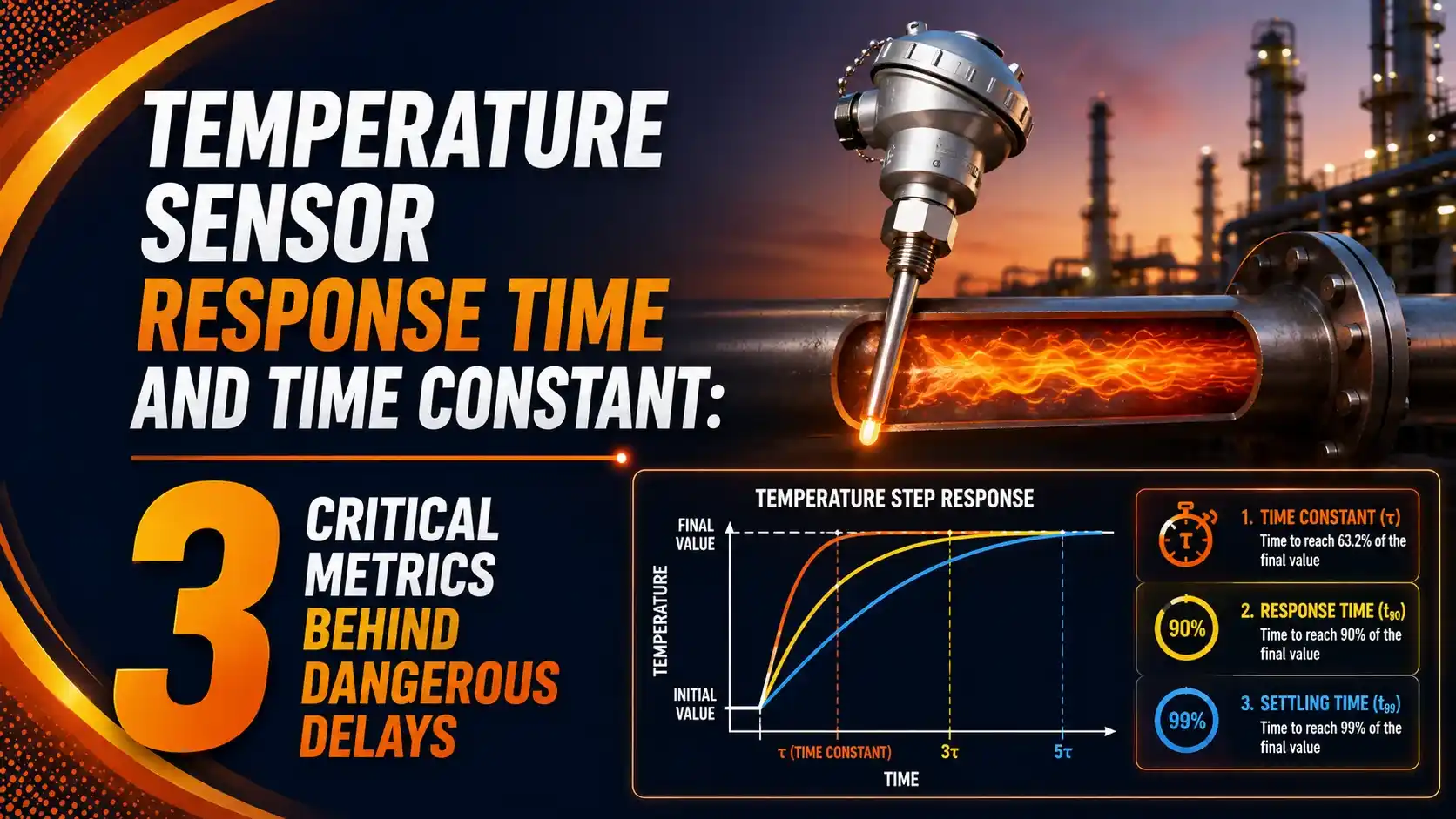
The 3 Critical Response Time Metrics
Temperature sensors are almost always specified using one, or all three, of these standard metrics.
Half-Time (50% Response)
Time to reach 50% of a step temperature change, equal to 0.693 times the time constant.
The Time Constant Itself
By definition, one full time constant, the classic 63.2% point used in the plunge test standard.
90% Response Time
Time to reach 90% of the change, equal to 2.303 times the time constant, the figure most datasheets actually quote.
Thermocouple vs RTD Response Time
Construction differences between the two sensor types translate directly into different thermal mass.
Thermocouple
Bare wire junctions can respond in milliseconds. Sheathed, grounded junction probes are still generally faster than an equivalent RTD.
RTD (Resistance Thermometer)
The platinum element, coil former, and sheath add thermal mass, but modern thin-film designs have narrowed the gap significantly.
The Thermal Time Constant Formula
This formula is the thermal equivalent of an RC circuit's time constant, just built from heat transfer variables instead of electrical ones.
A thicker sheath doesn't just add mass, it also changes surface area to volume ratio. Cutting sheath diameter in half can cut response time roughly in half too, for the same reason a thin wire heats up faster than a thick rod.
t50 = 0.693 x τ
t63.2 = 1.000 x τ
t90 = 2.303 x τ
Example: τ = 10 seconds (typical thermowell installation)
t50 = 6.93 s, t63.2 = 10 s, t90 = 23.0 s
Real Response Times: Sensor to Thermowell
Response time can vary by three orders of magnitude depending purely on installation, not sensor quality.
| Configuration | Typical t63.2 / t90 |
|---|---|
| Bare butt-welded thermocouple wire (0.001 in) | t63.2 = 0.003 s |
| Fast-response RTD, direct contact (e.g. iTHERM QuickSens) | t90 = 1.5 s |
| Standard sheathed RTD, direct contact | t90 = 9.5 s |
| RTD in thermowell, good thermal contact | t50 = 10 s, t90 = 40 s |
| RTD in thermowell with air gap | t90 = 60+ s |
Plunge Test vs LCSR: How Response Time Is Actually Measured
Two very different methods exist, and they're used at completely different stages of a sensor's life.
Plunge Test
A laboratory method: the sensor is suddenly immersed in flowing water at a set velocity, and the step response is timed directly.
LCSR (Loop Current Step Response)
An in-situ method: a current step self-heats the RTD's own element, and the heating and cooling transient reveals the actual installed response time.
LCSR testing is standard practice in nuclear power plants, where sensors can't be pulled for a plunge test without a shutdown, and validated LCSR results typically agree with plunge test values within about 10 percent.
Where Response Time Actually Matters
SIF and SIL Loops
Total sensor response time eats directly into available process safety time.
Combustion Control
Fast exhaust gas sensors need low thermal mass for tight control loops.
Food and Beverage
Fast pasteurization verification depends on quick, repeatable response.
Nuclear Power
RTD response time is a licensed technical specification, tested regularly.
Automotive Exhaust
Fast RTDs track rapidly changing exhaust gas temperatures for emissions control.
Batch Reactors
Slower thermowell-mounted sensors are often acceptable for large thermal mass processes.
When the Simple Formula Breaks Down: The Biot Number
The tau = mCp/hA formula assumes the entire sensor sits at one uniform temperature at every instant. That assumption isn't always true.
Engineers check this with the Biot number, the ratio of internal conduction resistance to surface convection resistance. Below about 0.1, the simple lumped model holds up well.
Typical thermowell assemblies fall between 0.5 and 5.0, well outside that safe range. For SIL-critical calculations, this means the simple exponential model is only a rough estimate, and a full transient heat conduction analysis is the more defensible approach.
Do's and Don'ts of Managing Response Time
✓ Do
- Fill thermowell air gaps with thermally conductive grease or paste
- Match sensor thermal mass to the actual speed the process needs
- Include total response time explicitly in SIF process safety time budgets
- Re-test response time periodically, since aging and buildup slow it down
✗ Don't
- Assume a manufacturer's bare-sensor spec applies once it's in a thermowell
- Ignore the air gap between sensor tip and thermowell bottom
- Ship response-critical sensors with oversized sheath diameters
- Treat a laboratory plunge test result as the true in-service response time
Live Temperature Sensor Response Calculator
Enter a step temperature change, the time constant, and elapsed time to calculate the sensor's actual reading.
Reference Materials on Temperature Sensor Response Time
FAQs on Temperature Sensor Response Time and Time Constant
External References
- How Thermowells Affect Temperature Response Times, WIKA
- Response Time Test of RTD and Thermocouple, Inst Tools
- How to Improve Temperature Measurement Response Times, Processing Magazine
- RTD Response Time Testing Using the LCSR Technique, AMS Corp
- Thermocouple Response Time, Omega Engineering
What we learn today
- Temperature sensor response time and time constant follow the same exponential math as an RC electrical circuit, just driven by heat transfer instead of resistance and capacitance.
- Three standard metrics describe it: t50 (0.693 tau), t63.2 (tau itself), and t90 (2.303 tau), with t90 quoted most often on datasheets.
- The formula tau = (density x volume x specific heat) / (heat transfer coefficient x area) shows why sheath diameter dominates response time.
- A thermowell can turn a 1.5 second sensor into a 40 second or slower response, especially with an air gap present.
- Plunge testing measures response time in a lab, while LCSR testing measures the real in-service response time without removing the sensor.