
A microcontroller pin can source barely twenty milliamps, yet switching a power MOSFET fast enough for a modern converter often needs a momentary surge well over an amp at the gate.
MOSFET Gate Driver ICs supply the fast, high current pulses a power MOSFET's gate capacitance needs, something a microcontroller pin or logic gate simply cannot deliver on its own.
Reading the basic MOSFET working principle first is useful background, since gate charge and the Miller plateau covered there are exactly what a gate driver chip is built to handle.
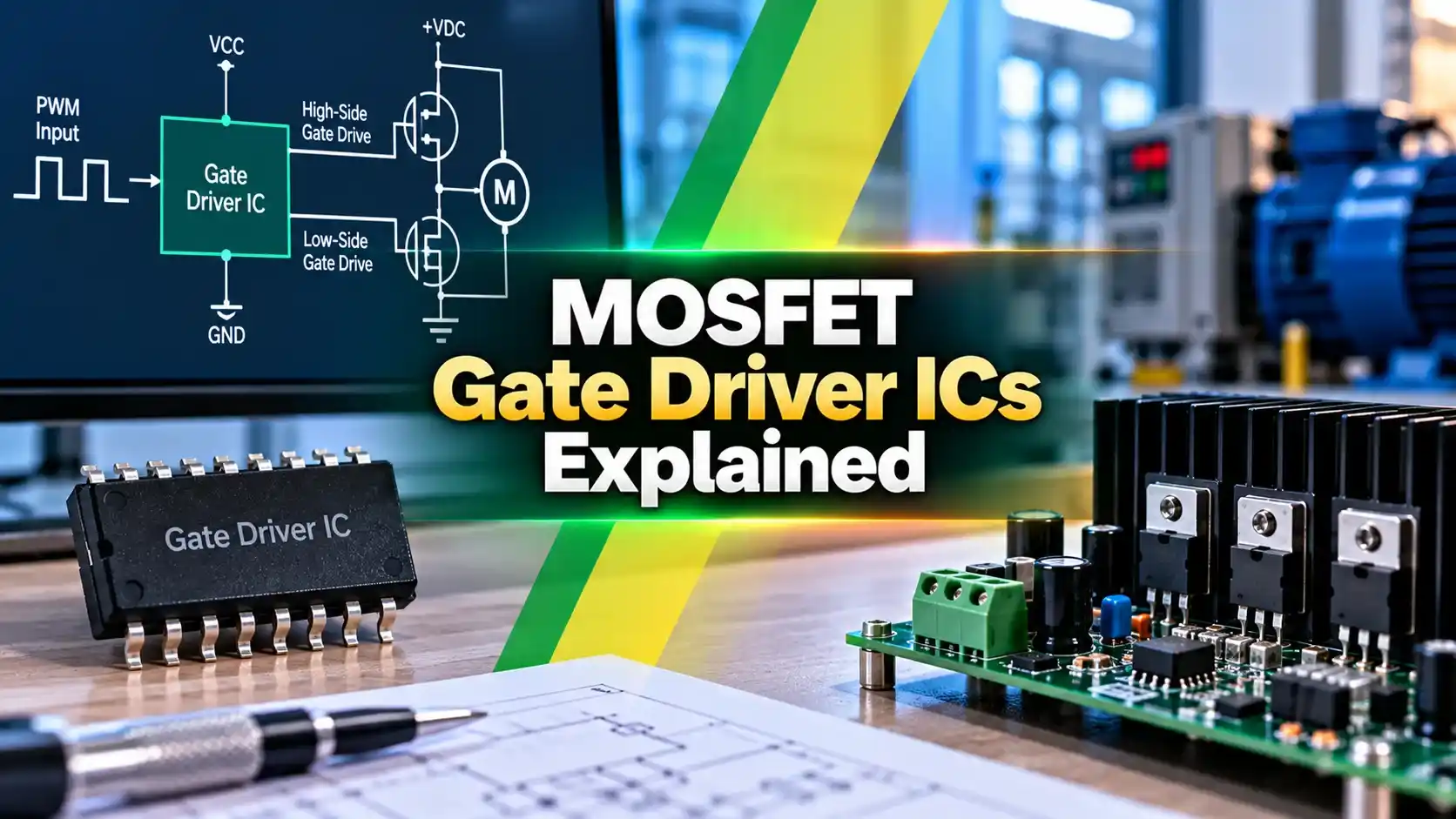
MOSFET Gate Driver ICs Explained
A power MOSFET's gate behaves like a small capacitor, and charging or discharging that capacitance quickly is what actually turns the device on and off, not just applying a voltage.
A typical power MOSFET needs tens of nanocoulombs of gate charge, and switching it in well under a microsecond means delivering a current pulse far beyond what a logic pin or op amp output can source.
MOSFET Gate Driver ICs exist specifically to supply that pulse, along with the voltage level shifting a high side switch position often requires.
Why a MOSFET Needs a Dedicated Gate Driver
A microcontroller general purpose output pin typically sources or sinks only eight to twenty milliamps, nowhere near enough current to charge a power MOSFET's gate quickly.
Driving the gate too slowly leaves the device lingering in its partially on linear region longer than necessary, generating far more heat during every single switching transition.
A dedicated driver chip can source and sink an amp or more for a brief pulse, moving the device through that lossy region as quickly as the application demands.
High Side vs Low Side Drive
A low side MOSFET has its source tied to ground, so driving its gate only ever needs a voltage referenced to that same ground, the simplest possible case.
A high side MOSFET has its source riding on a switching node that swings between ground and the supply rail, so its gate drive voltage has to float along with that node.
This floating requirement is the entire reason high side gate drive is harder than low side drive, and why bootstrap and isolated techniques exist at all.
Key Concepts Behind Gate Driver ICs
| Property | Non Isolated Driver | Isolated Driver |
|---|---|---|
| Ground reference | Shared with control circuit | Fully separated, galvanic isolation |
| Typical parts | IR2110, TC4420, UCC27524 | HCPL3120, ADuM3223, Si8234 |
| Isolation voltage | None | Often 5 kilovolts or more |
| Best for | Low voltage, cost sensitive designs | High voltage or safety critical systems |
How a Bootstrap Circuit Works
Common Applications
Common Mistakes With Gate Driver Circuits
Selecting a Gate Driver for a New Design
Peak source and sink current rating should comfortably exceed the peak current the target MOSFET actually needs during its fastest planned transition, not just its average gate current.
Propagation delay and its matching between the high side and low side channels of a single driver chip both affect how much dead time margin a design genuinely needs.
Undervoltage lockout, a feature that holds the output off until the supply reaches a safe level, protects against a partially charged bootstrap capacitor driving a MOSFET into its lossy linear region.
Package and Layout Considerations
Gate driver ICs are often placed as physically close to their target MOSFET as layout allows, since even a few centimeters of trace adds inductance that can ring and slow switching edges.
A dedicated, low inductance ground return path for the driver, separate from noisy power ground where possible, reduces the risk of false triggering from switching noise coupling back into the control input.
Many modern driver packages include built in features such as desaturation fault detection or active Miller clamp circuits, both worth checking against a specific application's protection requirements.
Built In Protection Features
None of these protection features are strictly mandatory for a simple low power design, but they become genuinely important once switching voltage, current, or frequency climb into demanding territory.
Non Isolated vs Isolated Gate Drivers
Non Isolated Driver
Lower cost and simpler layout, fine for low voltage systems with a shared ground reference.
Isolated Driver
Higher cost, but essential wherever high voltage or safety requirements demand true galvanic separation.
Newer silicon carbide and gallium nitride power devices switch fast enough that an isolated driver's CMTI rating becomes just as important as its isolation voltage rating.
Gate Drive Power Loss and Efficiency
Every time a gate is charged and discharged, the energy stored in that gate capacitance is dissipated as heat somewhere in the driving circuit, a real loss that scales directly with switching frequency.
At low switching frequency this gate drive loss is negligible next to conduction losses, but at very high frequency it can become a meaningful fraction of total system loss.
Choosing a MOSFET with lower gate charge, or accepting a slightly higher on resistance in exchange for lower gate charge, is a common tradeoff engineers make once switching frequency climbs into the hundreds of kilohertz.
Negative Gate Drive for Noise Immunity
Some high power designs drive the gate to a small negative voltage during the off state rather than simply zero volts, adding extra margin against noise induced false turn on.
This technique shows up most often in high current industrial motor drives and welding equipment, where switching node noise coupling back to the gate is a genuine, measured field problem.
A driver chip supporting negative gate drive needs a slightly more complex supply arrangement, generating both a positive turn on rail and a smaller negative turn off rail from the same input supply.
Watch: MOSFET Gate Driver Basics
MOSFET Gate Driver ICs FAQs
Whatever the topology, the underlying job of MOSFET Gate Driver ICs stays the same, deliver a fast, clean, correctly timed pulse strong enough to switch the device without lingering in its lossy region.
Related Articles on This Site
- What Is a MOSFET Working Principle
- IGBT Working Principle and Applications
- VFD Working Principle Explained
- Brushless DC Motor Working Principle
- How Decoupling Capacitors Work
External References
What We Learn Today
- A power MOSFET's gate capacitance needs a fast current pulse no ordinary logic pin can supply.
- High side switching needs a floating supply, solved through a bootstrap circuit or a fully isolated driver.
- Dead time and proper bootstrap sizing are what keep a half bridge circuit from destroying itself.