
A complete fuse selection guide covers more than ampere rating. The fuse type, voltage rating, breaking capacity, utilisation category, and coordination with upstream and downstream devices all determine whether the installation is properly protected.
This fuse selection guide covers fuse types, rating selection, and coordination across a distribution system.
Fuse selection in any fuse selection guide starts with four parameters: rated current, voltage rating, breaking capacity, and utilisation category. Get any one wrong and the fuse either nuisance trips on normal inrush or fails to interrupt a real fault.
Fuse Selection Guide: The 4 Parameters Every Engineer Must Check
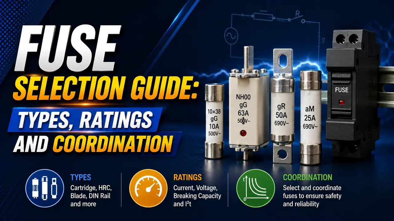
A fuse protects by melting when current exceeds the rated value. The time to melt depends on the current -- shown on a time-current curve (TCC).
Two parameters beyond ampere rating are critical in any fuse selection guide: the breaking capacity, which must exceed the prospective short-circuit current at the installation point, and the utilisation category, which defines whether the fuse handles motor inrush, semiconductor protection, or general cable protection.
Fuse Types and IEC Utilisation Categories
| Category | Type | Characteristic | Typical Application |
|---|---|---|---|
| gG | Full-range general purpose | Clears both overloads and short circuits across full current range | Cable and distribution board protection, feeders, final circuits |
| aM | Motor circuit | Does not clear low overloads -- relies on motor overload relay for those. Very fast on short circuit. | Motor branch circuits where a thermal overload relay handles overload protection |
| aR / gR | Semiconductor | Ultra-fast, very low I²t let-through. Does not protect against overloads -- semiconductor-rated only. | VFD input protection, thyristor (SCR) protection, UPS rectifier circuits |
| gPV | Photovoltaic DC | Rated for DC voltage and reverse current in PV string circuits | Solar PV string fusing, DC combiner boxes |
| gTr | Transformer | Time delay characteristic matches transformer inrush without operating on energisation | Transformer primary protection |
How to Select the Correct Fuse Rating: Fuse Selection Step by Step
Step 1 -- Rated Current
The fuse rated current must be greater than the maximum continuous load current. For cable protection, it must also be less than or equal to the cable ampacity.
For motor circuits using an aM fuse, the selection rule is 1.5 to 2.5 times the motor full load current.
This gives enough headroom for starting inrush (typically 6 to 7 times full load current) without nuisance operation.
I_FLC: motor full load current (from nameplate or data sheet)
Use 1.5x for standard motors with short start times. Use up to 2.5x for long start or high inertia loads. Always verify against the aM fuse manufacturer time-current curve.
Step 2 -- Voltage Rating
The fuse voltage rating must equal or exceed the system voltage. AC and DC ratings are not interchangeable.
A fuse rated for 400 V AC cannot be used in 400 V DC without a specific DC rating. DC arcs are harder to extinguish because there is no natural current zero crossing.
Step 3 -- Breaking Capacity
The breaking capacity must exceed the prospective short-circuit current (PSCC) at the point of installation. Calculate PSCC using the system impedance. See the short circuit current calculation guide for the method.
HRC fuses achieve breaking capacities of 50 kA to 120 kA.
At a typical industrial distribution board, fault currents are often 10 kA to 50 kA -- within HRC capability. At the main incomer near a large transformer, fault currents can exceed 50 kA and must be checked carefully.
Fuse Coordination and Selectivity
Fuse coordination (also called selectivity) means that when a fault occurs, only the fuse closest to the fault operates. The upstream fuse must not blow. This limits the outage to the faulted circuit only.
For fuse coordination, the clearing I²t of the downstream fuse must be less than the pre-arcing I²t of the upstream fuse.
When this holds, the downstream fuse clears before the upstream fuse begins to melt.
I²t pre-arcing: energy needed to start melting the upstream fuse element
Both values are read from the manufacturer's I²t datasheet at the prospective fault current level
Most fuse manufacturers publish a selectivity ratio table.
The simplest rule: the line side fuse rating must be at least 2 times the load side fuse rating for gG fuses to coordinate at all fault levels up to the interrupting rating.
Fuse Selection Calculator and Coordination Checker
Fuse Selection Guide for Common Applications
Motor Branch Circuit
Use aM fuses at 1.5 to 2.0 times motor full load current. Pair with a thermal overload relay for overload protection. See the MCB vs MCCB guide for when to use a circuit breaker instead of an aM fuse.
Distribution Board Feeder
Use gG fuses at or below the cable ampacity. See the earthing guide and the TN/TT/IT earthing guide for loop impedance and disconnection time.
VFD and Power Electronics
Use aR semiconductor fuses ahead of VFD input rectifiers and thyristor drives. The aR fuse has very low I²t let-through, protecting the semiconductor junction before it can be damaged. Never substitute a gG fuse -- it is far too slow for semiconductor protection.
Hazardous Area Installations
Fuse selection in hazardous areas must also satisfy the ATEX or IECEx certified equipment energy limitation requirements. Some Ex ia and Ex ib circuits specify maximum fuse current and I²t as part of the entity parameters. See the hazardous area classification guide.
Watch: Fuse Sizing and Selection Explained
Fuse Selection Guide Questions
External References
- Electrical Fuse Types, Ratings and Selection Guide -- Viox (updated 2026)
- Fuse Selection Guidelines -- Passive Components Industry (Littelfuse data)
What We Learn Today
- Every fuse selection guide starts with four checks: rated current, voltage rating, breaking capacity, and utilisation category (gG, aM, aR)
- gG fuses protect cables and feeders across the full overcurrent range. aM fuses are for motor circuits -- pair with a thermal overload relay
- Breaking capacity must be greater than or equal to the prospective short-circuit current at the installation point
- Fuse coordination requires the load side clearing I²t to be less than the line side pre-arcing I²t
- A 2:1 current ratio between line side and load side fuses is the minimum guideline for gG fuse coordination -- always verify with manufacturer data
- Use aR semiconductor fuses for VFD and thyristor protection -- never substitute a gG fuse in these applications